
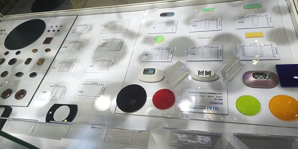
A custom beauty instrument optical filter is a coated optical component designed to transmit, block, attenuate, or reflect selected wavelength ranges inside an IPL, laser, LED, imaging, sensing, or medical-aesthetic device. The correct filter cannot be selected from a cutoff wavelength alone. Medical device manufacturers should also define the source spectrum, required passband, out-of-band blocking, angle of incidence, optical power, pulse conditions, substrate, coating durability, dimensions, clear aperture, operating environment, and inspection method.
Customization is appropriate when a stock filter does not match the complete optical system, when the filter must fit a proprietary handpiece or housing, or when stable spectral performance must be maintained under defined thermal, angular, mechanical, and environmental conditions. Prototype samples should be tested in the complete device before production specifications are finalized.
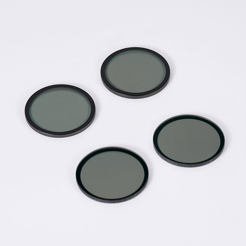
What Is a Custom Beauty Instrument Optical Filter?
Definition: A custom beauty instrument optical filter is an optical substrate with a wavelength-selective coating or material structure manufactured to meet the spectral, mechanical, environmental, and integration requirements of a specific beauty or medical-aesthetic device.
An optical filter controls the spectral content that continues through or is reflected by an optical assembly. Depending on the design, it may establish a cut-on wavelength, isolate a passband, suppress an unwanted wavelength range, reduce total optical intensity, or protect another optical component.
In a beauty instrument, the filter is not an isolated accessory. It operates as part of a system that may include:
- A flashlamp, LED, laser, or other light source
- Reflectors and collection optics
- Lightguides
- Cooling components
- Protective windows
- Detectors or monitoring sensors
- Mechanical holders
- Control electronics
- Software-defined operating modes
The filter specification must therefore be derived from the complete device architecture rather than copied from another product.
Why Beauty Instruments Require Wavelength Control
Many light-based instruments generate more wavelengths than the application requires. A filter modifies this source spectrum before the light reaches the output window, treatment head, detector, or imaging path.
For example, a broad-spectrum pulsed-light system can use interchangeable cutoff or band-selecting filters to create different output ranges. By contrast, a nominally narrowband source may use a filter to suppress residual emission, protect a detector, separate illumination from imaging, or reject reflected source light. Public technical records document both cutoff-filter and notch-filter configurations in pulsed-light equipment, demonstrating that filter architecture varies by system.
The optical filter may perform one or more of the following functions:
- Define the usable wavelength range
- Remove shorter wavelengths
- Reduce unwanted infrared output
- Suppress a specific source line
- Increase contrast in an imaging channel
- Separate illumination and detection wavelengths
- Reduce stray light
- Balance optical intensity
- Protect a sensor or downstream optic
- Support repeatable output between device operating modes
The filter controls only one part of device performance. It does not independently determine clinical suitability, treatment settings, product safety, or regulatory compliance.
Which Filter Types Are Used in Beauty and Medical-Aesthetic Devices?
Different filter architectures solve different optical problems. A supplier should not recommend a coating design until the source spectrum, desired output spectrum, optical geometry, and operating environment have been reviewed.
| Filter Type | Primary Optical Function | Potential Device Use | Critical Specifications |
|---|---|---|---|
| Longpass filter | Transmits wavelengths above a defined transition and blocks shorter wavelengths | Broad-spectrum light shaping, short-wavelength rejection | Cut-on wavelength, transition slope, passband transmission, short-wave blocking |
| Shortpass filter | Transmits shorter wavelengths and blocks longer wavelengths | Infrared suppression, detector protection, thermal-load control | Cutoff wavelength, infrared blocking range, thermal stability |
| Bandpass filter | Transmits a defined wavelength interval and blocks wavelengths on both sides | Selected output band, sensing, imaging, fluorescence-related modules | Center wavelength, bandwidth, transmission, blocking range, AOI |
| Narrow bandpass filter | Isolates a relatively narrow wavelength range | Sensor channels, source monitoring, fluorescence detection, wavelength-specific imaging | Center wavelength tolerance, FWHM, blocking, AOI, temperature sensitivity |
| Notch filter | Rejects a selected wavelength interval while transmitting ranges around it | Source-line rejection, imaging-channel separation, unwanted wavelength suppression | Notch center, notch width, blocking depth, adjacent transmission |
| Neutral density filter | Reduces optical intensity over a defined spectral range | Detector protection, calibration, source balancing | Optical density, spectral neutrality, power handling |
| Dichroic filter | Separates wavelength ranges by transmission and reflection | Multi-channel optical paths, illumination and imaging separation | Reflection band, transmission band, AOI, polarization |
| Coated optical window | Provides mechanical protection with controlled spectral performance | Handpiece window, sealed optical enclosure, sensor cover | Transmission, coating, flatness, strength, surface quality, environmental resistance |
For broad-spectrum source control, engineers often begin by evaluating long pass filters for beauty devices. A longpass design transmits wavelengths above a specified transition while attenuating shorter wavelengths. GIAI Photonics lists longpass filters as a dedicated category and currently presents multiple beauty-instrument and pulsed-light configurations within that category.
However, a longpass filter is not automatically the correct solution. A system requiring both short-wave and long-wave rejection may need a bandpass design, a notch structure, a coated window, or a combination of optical elements.
How to Choose the Required Wavelength Range
The wavelength specification should be developed from system-level data.
1. Measure or obtain the source spectrum
Begin with spectral data for the actual light source at relevant operating conditions. A nominal source description is not sufficient when the output changes with:
- Drive current
- Pulse energy
- Pulse duration
- Lamp age
- Temperature
- Optical alignment
- Reflector design
- Lightguide transmission
- Operating mode
The spectrum should cover both the intended transmission range and the wavelengths that must be rejected.
2. Define the required output spectrum
Specify the desired output at the filter location or final device output. The request should distinguish among:
- Minimum transmission range
- Preferred transmission range
- Transition region
- Blocking region
- Permitted leakage
- Unspecified region
Avoid requests such as “block ultraviolet” or “transmit visible and infrared” without numerical boundaries and test conditions.
3. Account for the detector or measurement system
In devices containing cameras, photodiodes, spectrometers, calibration sensors, or source-monitoring channels, the filter must be matched to detector responsivity as well as source output.
A small spectral leak may be insignificant to the treatment-output path but significant to a highly sensitive detector. This is one reason why bandpass filters for optical instruments often require broader blocking specifications than a basic visual inspection would suggest.
4. Separate filter specifications from device claims
A filter manufacturer can evaluate spectral feasibility and component performance. The medical device manufacturer remains responsible for establishing the complete device output, intended use, risk controls, validation criteria, labeling, and applicable compliance strategy.
Light-based medical and aesthetic equipment may be subject to market-specific safety and essential-performance requirements. Optical filter approval should therefore be incorporated into the manufacturer’s controlled design and verification process.
Critical Optical Specifications
Cut-on or cutoff wavelength
For a longpass filter, the cut-on wavelength defines the transition from the blocked region toward the transmitted region. The specification should state how the wavelength is measured.
Possible definitions include:
- Wavelength at 50% transmission
- Wavelength at a specified transmission threshold
- Maximum wavelength of the blocking region
- Minimum wavelength of the passband
Two filters described with the same nominal cutoff can have different transition slopes and usable spectra.
Passband transmission
Passband transmission determines how much wanted light passes through the filter.
The requirement may be expressed as:
- Minimum transmission at selected wavelengths
- Average transmission across a band
- Peak transmission
- Transmission uniformity
- Transmission at a specified AOI and polarization
A higher transmission target can improve optical throughput, but it may increase coating complexity when combined with deep blocking, steep transitions, wide blocking ranges, or high angular stability.
Blocking range and optical density
Blocking should include both the required wavelength interval and the allowable residual transmission.
Optical density is related to transmission by:
OD = −log₁₀(T)
where transmission is expressed as a decimal.
For example, deeper blocking represents lower residual transmission. The required OD should be selected according to the source intensity, detector sensitivity, system risk analysis, and allowable leakage—not from a generic filter description.
The specification should identify:
- Blocking wavelength range
- Minimum OD
- Test resolution
- Measurement floor
- AOI
- Polarization
- Temperature, when relevant
Transition slope
The transition slope describes how quickly a filter changes between blocking and transmission.
A steeper transition may be useful when the wanted and unwanted wavelengths are close together. However, steep edges can make the design more sensitive to:
- Manufacturing tolerances
- Angle of incidence
- Cone angle
- Polarization
- Temperature
- Coating thickness variation
The engineering team should define the usable spectral boundary rather than requesting the steepest possible transition without a system-level reason.
Spectral ripple
Ripple refers to transmission variation within the passband. It may affect:
- Output uniformity across wavelength
- Detector calibration
- Spectral measurement
- Imaging color balance
- Mode-to-mode consistency
The acceptable ripple should be quantified when the application depends on spectral uniformity.
Why Angle of Incidence Must Be Specified
Angle of incidence, or AOI, is the angle between the incoming ray and the surface normal of the filter.
For many interference filters, changing the AOI changes the effective optical thickness of the coating. As AOI increases, the spectral response commonly shifts toward shorter wavelengths. A converging or diverging beam can also broaden or modify the measured response because different rays strike the filter at different angles.
Medical device manufacturers should provide:
- Nominal AOI
- Minimum and maximum AOI
- Beam cone angle
- Collimated, converging, or diverging beam condition
- Source-to-filter geometry
- Filter orientation
- Polarization state, when relevant
A filter measured at normal incidence may not deliver the same spectrum when installed at an angle inside a handpiece.
AOI example
Suppose a longpass filter is specified only by its cut-on wavelength at normal incidence. If the production assembly installs the filter at an oblique angle, the transition may shift. This can change both the transmitted output and the blocked region.
The better approach is to specify the required spectrum at the actual operating AOI or across the complete angular range.
Substrate Material Selection
The substrate supports the coating and influences transmission, thermal behavior, mechanical durability, thickness, weight, and manufacturing feasibility.
Substrate selection should consider:
- Required wavelength range
- Internal absorption
- Refractive index
- Thermal expansion
- Thermal conductivity
- Thermal-shock resistance
- Mechanical strength
- Chemical resistance
- Available thickness
- Surface-quality requirements
- Cost and production quantity
Optical glass is commonly evaluated for visible and near-infrared filters, but the correct grade depends on the spectrum and operating environment. Other materials may be required for specialized infrared, ultraviolet, high-power, or thermally demanding systems.
The substrate should not be chosen solely from transmission data. A material with adequate initial transmission may still be unsuitable if it experiences excessive thermal stress, coating mismatch, deformation, moisture sensitivity, or mechanical damage in the assembled device.
Coating Design and Durability
A multilayer optical coating creates wavelength-selective transmission or reflection. The design may need to balance:
- Passband transmission
- Blocking depth
- Blocking bandwidth
- Transition steepness
- AOI stability
- Thermal performance
- Environmental durability
- Manufacturability
- Batch repeatability
- Cost
Medical-device teams should communicate the expected environment, including:
- Operating temperature
- Storage temperature
- Humidity
- Cleaning method
- Condensation risk
- Chemical exposure
- Skin-contact proximity
- Repeated pulse exposure
- Mechanical handling
- Expected service life
The coating specification should also clarify which surface is coated, how the filter will be oriented, and whether edge sealing or special handling is required.
Thermal Load and Pulsed-Light Conditions
Average optical power alone may not describe the stress experienced by a filter in a pulsed system.
The supplier may need:
- Source type
- Pulse energy
- Pulse duration
- Repetition rate
- Beam or illuminated area
- Peak and average power
- Duty cycle
- Cooling method
- Distance from the source
- Housing temperature
- Maximum operating duration
- Expected contamination level
Unwanted wavelengths rejected by a filter must be reflected, absorbed, or divided between both mechanisms. The thermal behavior therefore depends on the coating design, substrate, mounting method, and surrounding assembly.
A filter that is acceptable in a low-power measurement path may not be appropriate close to a high-intensity pulsed source.
Mechanical and Surface Requirements
A complete drawing should define more than length, width, and thickness.
Relevant mechanical specifications may include:
- Outer dimensions
- Diameter
- Thickness
- Dimensional tolerances
- Clear aperture
- Coated aperture
- Edge exclusion
- Chamfers
- Bevels
- Corner radius
- Wedge
- Parallelism
- Flatness
- Surface quality
- Edge finish
- Orientation mark
- Coating-side mark
The clear aperture is especially important. The coating may meet spectral requirements in the central area while the device beam extends into an edge-exclusion region.
For components exposed at the handpiece surface, optical windows for protective assemblies may need separate evaluation for strength, flatness, sealing, scratch resistance, coating durability, and cleanability.
Stock Filter vs. Custom Beauty Instrument Optical Filter
| Evaluation Factor | Stock Filter | Custom Filter |
|---|---|---|
| Development speed | Usually faster when a suitable model exists | Requires specification review and production planning |
| Spectral match | Limited to published design | Can be optimized around the required source and output |
| Mechanical fit | Standard sizes and thicknesses | Can follow a proprietary drawing |
| AOI optimization | Fixed published condition | Can be reviewed for the actual system geometry |
| Blocking range | Predetermined | Can be developed around source leakage and detector response |
| Thermal review | Based on general product limits | Can consider source, pulse, mounting, and cooling conditions |
| Prototype testing | Useful but may be readily available | Usually important before production approval |
| Production control | Standard product configuration | Drawing, revision, acceptance, and change control can be defined |
| Cost | Often lower for small quantities | Depends on coating complexity, tooling, testing, size, and volume |
A stock filter is appropriate when its verified spectral, mechanical, thermal, and environmental specifications already match the device.
A custom filter is appropriate when one or more critical requirements cannot be satisfied by an existing component.
When to Choose Custom Optical Components
Consider custom optical filters when:
- The source spectrum does not match an available filter.
- The device requires a proprietary cutoff or passband.
- Both short-wave and long-wave blocking are needed.
- Out-of-band leakage affects a detector or safety analysis.
- The filter operates at a non-standard AOI.
- The beam has a wide cone angle.
- Standard dimensions do not fit the housing or handpiece.
- The filter must also function as a protective window.
- Pulse energy or thermal exposure requires specific evaluation.
- Environmental or cleaning conditions differ from standard use.
- The device requires controlled batch acceptance criteria.
- A discontinued or unavailable filter must be replaced.
- An existing sample must be characterized and reproduced.
- Multiple optical functions must be combined into fewer components.
Customization should not begin with coating production. It should begin with a specification review.
Eight-Step Custom Filter Selection Process
Step 1: Describe the device and optical function
Explain whether the filter is used in:
- A broad-spectrum pulsed-light system
- A laser system
- An LED device
- An imaging path
- A source-monitoring module
- A fluorescence-related detection system
- A skin-analysis instrument
- A protective output assembly
State where the filter is installed and what optical problem it must solve.
Step 2: Provide source-spectrum data
Supply measured data where possible. Include all relevant operating modes and identify the measurement conditions.
Step 3: Define passband and blocking requirements
Use a wavelength-versus-transmission table rather than only a product name.
Step 4: Define the optical geometry
Specify AOI, angular range, cone angle, beam size, polarization, and installation orientation.
Step 5: Define mechanical requirements
Provide a controlled drawing with dimensions, tolerances, clear aperture, coating area, chamfers, and orientation markings.
Step 6: Define environmental and thermal conditions
Include temperature, humidity, cleaning, pulse conditions, cooling, contamination, and mounting information.
Step 7: Agree on inspection criteria
Confirm how transmission, blocking, dimensions, surface quality, and coating appearance will be evaluated.
Step 8: Test prototypes in the complete device
Prototype approval should consider not only the filter’s spectrometer report but also the assembled device output, thermal behavior, consistency, and relevant system-level verification.
Practical Selection Checklist
Before requesting a quotation, confirm the following information.
Optical requirements
- Light-source type
- Measured source spectrum
- Required passband
- Cut-on or cutoff definition
- Minimum transmission
- Blocking wavelength range
- Minimum optical density
- Permitted spectral leakage
- Transition-slope requirement
- Ripple tolerance
- Reflection requirements
- AOI and angular range
- Beam cone angle
- Polarization condition
Mechanical requirements
- Length and width or diameter
- Thickness
- Dimensional tolerances
- Clear aperture
- Coating aperture
- Chamfer or bevel
- Flatness
- Parallelism or wedge
- Surface quality
- Coating-side identification
- Mounting method
Operating conditions
- Peak and average optical power
- Pulse energy and duration
- Repetition rate
- Operating and storage temperatures
- Cooling method
- Humidity
- Cleaning process
- Chemical exposure
- Expected service conditions
Procurement information
- Prototype quantity
- Estimated production quantity
- Annual demand
- Required documentation
- Inspection report requirements
- Packaging requirements
- Approved drawing revision
- Sample evaluation requirement
Common Mistakes When Specifying Beauty Instrument Filters
Mistake 1: Specifying only a nominal wavelength
A request such as “550 nm filter” is incomplete. It does not indicate whether 550 nm refers to a center wavelength, cut-on wavelength, cutoff wavelength, transmission threshold, or blocking boundary.
Mistake 2: Ignoring out-of-band leakage
A filter can have high transmission in the required band but still allow unwanted wavelengths outside that band. Blocking must cover the source output and detector sensitivity relevant to the system.
Mistake 3: Omitting angle of incidence
Spectral data measured at one AOI cannot automatically be applied to a different installation angle.
Mistake 4: Treating optical density as a single number
OD should always be associated with a wavelength range and measurement condition.
Mistake 5: Selecting the substrate only by visible appearance
Two substrates that look similar may have different absorption, thermal expansion, durability, and coating compatibility.
Mistake 6: Assuming maximum transmission is always better
Transmission must be balanced against blocking, transition steepness, durability, thermal behavior, and repeatability.
Mistake 7: Failing to define the clear aperture
The mechanical size is not necessarily the usable coated area.
Mistake 8: Sending a sample without system information
A sample can be measured, but reverse evaluation is more useful when the supplier also understands the device function, source, AOI, environment, and desired changes.
Mistake 9: Approving a filter from visual color alone
Visible appearance cannot confirm passband transmission, blocking depth, spectral leakage, or AOI performance.
Mistake 10: Changing the filter without system-level review
A new filter may change optical output, thermal loading, detector response, calibration, or device performance. Medical device manufacturers should process the change through their applicable design, risk, verification, and regulatory procedures.
What to Send for Drawing or Sample Review
A useful custom filter inquiry should include:
| Information | Recommended Content |
|---|---|
| Application background | Device type, optical function, filter location |
| Source information | Source type, spectrum, operating modes |
| Spectral target | Passband, blocking band, OD, transmission |
| Optical geometry | AOI, cone angle, polarization, beam size |
| Mechanical drawing | Size, thickness, tolerances, clear aperture |
| Material preference | Preferred substrate or permission to recommend |
| Environment | Temperature, humidity, cleaning, chemicals |
| Power conditions | Pulse energy, duration, repetition, cooling |
| Existing sample | Sample quantity and required analysis |
| Quality criteria | Spectral report, dimensional inspection, appearance |
| Quantity | Prototype, pilot, and estimated production volumes |
| Development objective | New design, replacement, cost review, or performance change |
GIAI Photonics states that custom optical components can be evaluated from customer drawings and that physical samples can also be examined when a complete drawing is unavailable. Its listed capabilities include filter, lens, prism, and coating-related work.
Prototype Evaluation and Incoming Inspection
A prototype evaluation plan should be agreed upon before samples are manufactured.
Supplier-side evaluation may include
- Spectral transmission measurement
- Blocking measurement within the instrument capability
- Dimensional inspection
- Thickness inspection
- Clear-aperture verification
- Surface-quality inspection
- Coating appearance inspection
- Orientation identification
- Packaging verification
Device-manufacturer evaluation may include
- Installed output-spectrum measurement
- Mode-to-mode comparison
- Optical-energy consistency
- Temperature monitoring
- Repeated-pulse testing
- Imaging or detector response
- Stray-light assessment
- Mechanical fit
- Cleaning compatibility
- Assembly repeatability
- System verification under intended conditions
The test method matters as much as the numerical requirement. Spectral measurements can differ with instrument resolution, beam geometry, polarization, AOI, and measurement floor. Both parties should agree on the acceptance method before production.
Procurement Considerations for Production Programs
Procurement teams should evaluate more than unit price.
Important commercial and quality questions include:
- Is the specification technically manufacturable?
- Which requirements drive coating complexity?
- Is special tooling required?
- What prototype quantity is practical?
- Can the same substrate remain available for production?
- How will spectral performance be documented?
- What are the cosmetic acceptance criteria?
- How will drawing revisions be controlled?
- Are golden samples required?
- How will batch changes be communicated?
- Is packaging suitable for coated optical surfaces?
- Can future demand changes be supported?
- What information is required before a repeat order?
A lower-cost filter that requires device redesign, produces inconsistent output, or lacks defined acceptance criteria can create a higher total project cost than a properly specified component.
How to Improve a Custom Filter Request
A weak inquiry might say:
We need a filter for a beauty machine. Please quote a 550 nm filter.
A stronger inquiry would say:
We are developing a pulsed-light handpiece. The filter is installed at the output of the source assembly at the AOI shown in the attached drawing. Please evaluate the attached source spectrum and propose a filter that meets the listed transmission and blocking requirements. The drawing includes size, thickness, clear aperture, and mounting details. Prototype samples will be tested in the complete device before production approval.
The second request gives the optical supplier enough context to identify missing information, discuss trade-offs, and evaluate manufacturing feasibility.
FAQ
1. What is a custom beauty instrument optical filter?
A custom beauty instrument optical filter is a wavelength-selective optical component designed for the source, geometry, dimensions, thermal conditions, and performance requirements of a specific beauty or medical-aesthetic device. It may transmit a selected band, block unwanted wavelengths, reduce intensity, separate optical channels, or function as a coated protective window.
2. Which filter is commonly evaluated for an IPL beauty instrument?
Longpass, bandpass, shortpass, and notch filters may all be evaluated, depending on the source spectrum and required output. Broad-spectrum systems often use cutoff filters, but the correct design should be determined from the complete required spectrum rather than the application name alone.
3. What information is required to customize an IPL optical filter?
Provide the source spectrum, target output spectrum, minimum transmission, blocking range, optical density, AOI, cone angle, dimensions, clear aperture, substrate preference, pulse conditions, temperature, cleaning requirements, prototype quantity, and production estimate.
4. What is the difference between a longpass filter and a bandpass filter?
A longpass filter transmits wavelengths longer than its transition region and blocks shorter wavelengths. A bandpass filter transmits a defined wavelength interval while blocking wavelengths on both sides. A bandpass filter may be preferable when both short-wave and long-wave rejection are required.
5. How does angle of incidence affect a beauty instrument optical filter?
Changing the AOI can shift the spectral response of an interference filter, commonly toward shorter wavelengths as the incidence angle increases. A beam containing a range of angles can also broaden the transition or passband. The filter should be specified and evaluated under the actual device geometry.
6. Does a higher optical density always mean a better filter?
No. The required optical density depends on the source intensity, detector sensitivity, blocked wavelength range, acceptable leakage, and system risk analysis. Increasing OD can add coating complexity and should be justified by the device requirements.
7. Can an existing optical filter sample be duplicated?
An existing sample can be measured and evaluated, but exact duplication may depend on identifying the substrate, coating structure, spectral performance, geometry, and manufacturing tolerances. The supplier should also understand the sample’s function and any performance changes required for the new device.
8. Is a custom filter enough to establish the safety of a medical-aesthetic device?
No. A filter is one component within the complete optical system. The device manufacturer must evaluate optical output, thermal behavior, electrical safety, software controls, risk management, intended use, labeling, verification, and applicable market requirements for the finished device.