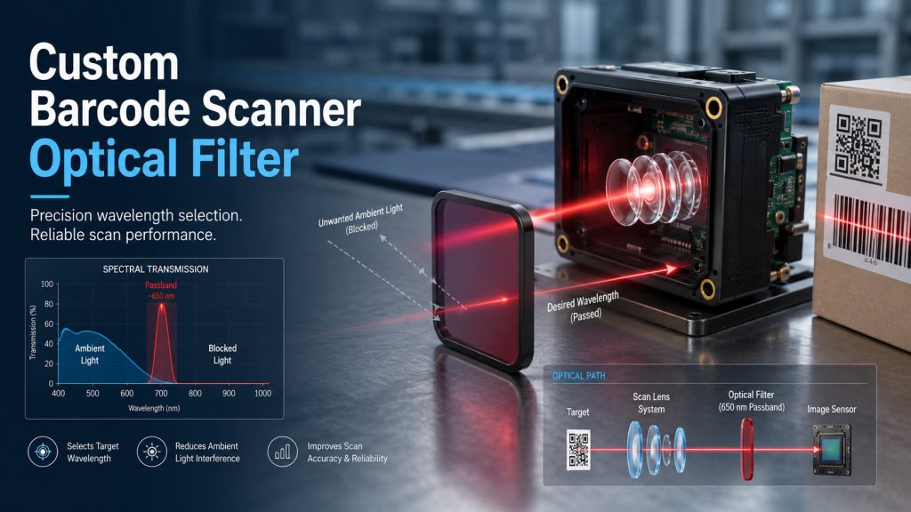
A custom barcode scanner optical filter is a wavelength-selective component designed to transmit the light used by a scanner while reducing unwanted ambient or out-of-band light reaching the detector. The correct filter depends on the scanner architecture, illumination spectrum, sensor response, barcode material, field of view, angle of incidence, operating environment, and mechanical assembly.
A red-illuminated scanner may use a bandpass filter matched to its LED or laser source. An infrared scanner requires a different passband and compatible substrate. A white-light imaging scanner may need a broader visible filter or an optical window rather than a narrow red filter. The filter must therefore be specified as part of the complete optical system, not selected only by a nominal wavelength such as 660 nm.
Simple definition:
A custom barcode scanner optical filter transmits the scanner’s useful illumination or imaging wavelengths while blocking spectral energy that could reduce barcode contrast, overload the detector, or introduce background noise.
What Does an Optical Filter Do in a Barcode Scanner?
A barcode scanner identifies differences in reflected light between the light and dark areas of a printed or marked code. The optical receiver may use a photodiode, line sensor, or area image sensor, depending on whether the scanner reads linear barcodes, two-dimensional codes, direct part marks, or general machine vision images.
The filter is normally positioned in front of the detector, imaging lens, or scanner entrance window. Its principal functions may include:
- Transmitting the scanner’s illumination wavelength
- Reducing sunlight, fluorescent lighting, LED lighting, or other ambient energy
- Improving the signal-to-background ratio
- Preventing unwanted infrared or ultraviolet wavelengths from reaching the sensor
- Protecting internal optical components
- Supporting the required appearance of the scanner window
- Reducing spectral variation between operating environments
Optical filters can transmit, reject, or reflect selected spectral regions. Bandpass-filter specifications are commonly described by center wavelength, cut-on and cut-off wavelengths, bandwidth, transmission, and blocking performance.
A filter cannot compensate for every barcode-reading problem. Illumination angle, lens focus, depth of field, sensor exposure, barcode print quality, motion blur, surface curvature, and image-processing settings also affect decoding performance.
Why One Filter Design Does Not Fit Every Barcode Scanner
Barcode scanners do not all use the same optical architecture. Industrial imaging systems may use red, blue, white, infrared, or multicolor illumination. Current scanner configurations include red illumination around 625–660 nm, infrared illumination around 850 nm, and broadband white illumination, depending on the target and imaging task.
The suitable filter must match the source and detector combination.
| Scanner Architecture | Typical Optical Requirement | Possible Filter Approach | Main Design Risk |
| Red LED area imager | Preserve reflected red illumination and suppress unrelated ambient light | Bandpass filter matched to the measured LED spectrum | Passband too narrow for LED width, temperature drift, or field angle |
| Red laser or line-scanning receiver | Isolate a relatively concentrated source wavelength | Narrow or moderate bandpass filter | Wavelength tolerance and AOI shift reduce useful transmission |
| White-light 2D imager | Preserve a broad visible range for colored codes or general imaging | Broad visible filter, UV/IR cut filter, or clear coated window | Narrow filtering removes useful color information |
| Infrared scanner | Pass the selected near-infrared illumination | Infrared bandpass filter | Incorrect substrate, coating, or detector matching |
| Multicolor machine vision reader | Support more than one illumination channel | Broad bandpass, multiband filter, or changeable filter arrangement | A single passband does not support all lighting channels |
| Scanner for glossy or metallic targets | Control specular reflection as well as wavelength | Spectral filter combined with suitable illumination and polarization | Treating a glare problem as a wavelength problem only |
A verification wavelength used to grade barcode print quality should not automatically become the scanner filter specification. Verification conditions describe how a symbol is evaluated; the scanner filter must be based on the actual source spectrum, detector response, target materials, and operating environment.
Narrow Bandpass, Broad Bandpass, or Optical Window?
Narrow Bandpass Filter
Narrow bandpass filters transmit a limited spectral interval and block wavelengths on both sides of the passband. They are useful when the scanner has a controlled, wavelength-specific source and when ambient-light rejection is important.
Engineers evaluating narrow bandpass filters should review:
- Source peak wavelength
- Source spectral width
- Wavelength tolerance between source batches
- Source wavelength change with temperature
- Detector spectral response
- Filter center wavelength tolerance
- Filter bandwidth
- AOI and cone angle
- Required blocking range
- Production-unit variation
A narrower filter may reject more background light, but it also provides less margin for source variation and angular spectral shift. Increasing AOI or cone angle can shift an interference-filter passband toward shorter wavelengths and alter its shape.
Moderate or Broad Bandpass Filter
A broader passband may be more practical when:
- The illumination source has a relatively broad spectrum
- The scanner has a large field of view
- Rays reach the filter over a wide cone angle
- The source wavelength changes across temperature
- The system uses more than one nearby illumination wavelength
- Manufacturing tolerance is more important than maximum spectral rejection
Properly specified bandpass filters for barcode scanners balance useful transmission, background rejection, angular performance, and production tolerance.
For applications that must preserve a wider visible region, broad bandpass filters may be more suitable than a narrow wavelength-selective design.
Infrared Filter
Infrared illumination may be used where visible illumination is undesirable or where the target has useful contrast in the near-infrared region. The filter must be matched to the infrared source and sensor response.
The engineer should verify:
- Actual infrared source wavelength
- Source bandwidth and tolerance
- Sensor quantum response
- Whether visible light should be blocked
- Substrate transmission at the selected wavelength
- Coating performance across the required blocking range
- Whether a visible aiming source must also pass
Separate infrared filters for sensing systems may be needed when one optical path uses visible aiming and another uses infrared image capture.
Clear or Spectrally Controlled Optical Window
Some scanners do not require a narrow bandpass filter. A protective window with antireflection, infrared-cut, color-control, hard-coating, or environmental-protection functions may be sufficient.
An optical window may be preferable when:
- The scanner uses broadband white illumination
- The camera must retain color information
- The main purpose is mechanical protection
- The sensor already contains suitable spectral filtering
- Ambient rejection is handled through synchronized illumination and short exposure
- The front window must support sealing or cleaning requirements
In these systems, optical windows for protective assemblies should be reviewed together with the lens, sensor cover glass, housing, and illumination geometry.
Key Specifications for a Custom Barcode Scanner Optical Filter
The specification should define the functional optical requirement instead of listing only a nominal wavelength.
| Parameter | What It Defines | Why It Matters in a Barcode Scanner |
| Passband or center wavelength | Spectral region transmitted by the filter | Must overlap the useful illumination and detector response |
| Cut-on and cut-off wavelengths | Edges of the transmitted region | Determine which wavelengths enter the receiver |
| FWHM or bandwidth | Width of the passband | Affects ambient rejection and tolerance to source variation |
| Peak or average transmission | Amount of useful light passing through | Influences received signal and exposure requirements |
| Blocking range | Wavelength interval that must be rejected | Should reflect the source spectrum, detector response, and ambient environment |
| Optical density | Logarithmic expression of out-of-band attenuation | Must be specified over defined wavelength ranges rather than as an isolated number |
| AOI | Nominal angle at which light reaches the filter | Interference-filter spectra change with incidence angle |
| Cone angle or f-number | Distribution of ray angles reaching the filter | Wide angular cones can shift and broaden the effective passband |
| Substrate material | Base optical material beneath the coating | Affects transmission, thickness, strength, thermal behavior, and manufacturability |
| Clear aperture | Usable coated optical area | Must cover the active receive path without edge interference |
| Thickness and tolerance | Physical filter thickness | Affects housing fit, focus, sealing, and replacement compatibility |
| Flatness or transmitted wavefront | Optical deformation introduced by the component | May matter when the filter is within an imaging path |
| Surface quality | Permitted cosmetic defects | Important near focused imaging paths and for customer-visible windows |
| Wedge or parallelism | Angular relationship between filter surfaces | Can introduce beam deviation or image displacement |
| Environmental requirements | Temperature, humidity, cleaning, abrasion, and storage conditions | Determine coating and substrate suitability |
| Edge treatment | Chamfer, blackened edge, ground edge, or orientation mark | Supports assembly, safety, stray-light control, and coating identification |
Center wavelength and FWHM are useful descriptors, but a production specification is often clearer when it defines the required transmission band, minimum transmission, blocking bands, and maximum out-of-band transmission. This approach gives both the system engineer and coating designer a more complete acceptance window.
How to Match the Filter to the Illumination Source
1. Obtain the Source Spectrum
Do not rely only on the LED or laser’s marketing wavelength. Obtain a spectral distribution, component data, or measured source spectrum under representative operating conditions.
For an LED source, review:
- Peak wavelength
- Spectral width
- Bin variation
- Operating current
- Junction temperature
- Optical diffuser or light-pipe effects
For a laser source, review:
- Nominal wavelength
- Wavelength tolerance
- Temperature shift
- Mode behavior where relevant
- Beam angle at the filter
2. Overlay the Detector Response
The filter does not operate independently of the sensor. A detector may remain sensitive far outside the desired illumination band. The blocking range should therefore be based partly on where the detector can generate unwanted signal.
Deep blocking in a spectral region where the detector has little response may add cost without improving the scanner. Weak blocking in a region where the detector is highly sensitive may allow avoidable background energy to reach the receiver.
3. Include Angular Effects
The filter should be evaluated at the actual AOI and over the real cone of rays produced by the lens system.
This becomes especially important when:
- The filter is close to a wide-angle imaging lens
- The scanner has a large field of view
- The component is intentionally tilted
- The filter is mounted in front of an off-axis receiver
- The filter must work across several lens configurations
As incidence angle increases, an interference-filter passband generally shifts toward shorter wavelengths. A range of ray angles can also soften the passband edges and reduce the effective flat-top region.
4. Add Practical Spectral Margin
The transmitted range should include sufficient margin for:
- Source tolerance
- Filter manufacturing tolerance
- Temperature behavior
- AOI shift
- Cone-angle broadening
- Assembly-angle variation
- Long-term system requirements
The most aggressive narrowband design is not necessarily the most reliable production design.
How Blocking and Transmission Affect Scanner Performance
High in-band transmission allows more useful reflected light to reach the detector. Strong out-of-band blocking reduces unwanted spectral energy. These requirements must be balanced rather than optimized independently.
Increasing blocking depth or widening the blocking range can increase coating complexity and cost. The useful blocking range should therefore be derived from:
- Ambient-light spectrum
- Detector sensitivity
- Internal light leakage
- Illumination source spectrum
- Housing geometry
- Required operating distance
- Exposure time
- Acceptable decoding margin
A requirement such as “high blocking” is incomplete. The RFQ should identify the wavelength range and the maximum permitted transmission or required OD across that range.
Similarly, “high transmission” should specify whether the requirement applies at one wavelength, across the complete passband, or as an average value.
Barcode Material and Illumination Wavelength
A filter can improve spectral isolation, but the barcode itself must produce sufficient contrast at the selected illumination wavelength.
This matters when reading:
- Colored bars or backgrounds
- Red printing under red illumination
- Thermal labels
- Reflective packaging
- Transparent films
- Metallic surfaces
- Laser-etched direct part marks
- Dot-peened codes
- Curved containers
- Low-contrast industrial markings
A barcode that appears dark to the human eye may not produce the same contrast at the scanner wavelength. The sample should therefore be evaluated under the proposed illumination and filter combination.
White illumination may be more suitable for multicolored labels, while wavelength-specific illumination can improve separation between selected colors. Current machine vision guidance also treats lighting color, spectral filtering, and polarization as separate but complementary contrast-control tools.
Reflective Labels and Direct Part Marks
Specular reflection from laminated labels, polished metal, plastic films, or curved containers can saturate part of the sensor image.
A spectral bandpass filter may reduce ambient light, but it does not necessarily remove reflection from the scanner’s own illumination because that reflection is within the desired passband.
Possible system-level responses include:
- Changing the illumination angle
- Using diffuse or dark-field illumination
- Tilting the scanner or target
- Using polarized illumination and a cross-oriented receiver polarizer
- Adjusting exposure or illumination intensity
- Separating the illumination and receive axes
- Selecting another illumination wavelength
- Using image-processing methods designed for direct part marks
Polarizing arrangements can reduce surface reflections when the illumination and receiver are configured correctly, although they also reduce the amount of useful light reaching the sensor.
Mechanical and Imaging Requirements
A custom barcode scanner filter may also act as a structural or protective component. Mechanical specifications should therefore be reviewed with the optical design.
Dimensions and Thickness
Provide:
- Outer length and width or diameter
- Thickness and thickness tolerance
- Chamfer dimensions
- Corner radius
- Clear aperture
- Coated area
- Uncoated border
- Datum surfaces
- Orientation requirements
A replacement component should not be specified from nominal housing dimensions alone. The original drawing or a measured sample is preferable.
Flatness, Wedge, and Focus
A plane-parallel plate inserted into a converging imaging path can affect optical path length and focus. Thickness changes, substrate refractive index, wedge, and transmitted wavefront error may influence image position or quality.
When the filter is positioned in front of optical lenses for scanner imaging, the lens designer should confirm:
- Filter location relative to the lens
- Chief-ray angle
- Maximum cone angle
- Filter thickness
- Refractive index
- Required flatness
- Allowed wedge
- Effect on focus and distortion
Do not apply unnecessarily tight imaging specifications to a filter that is positioned far from a critical image plane. Conversely, do not treat a precision imaging-path component as a cosmetic cover window.
Substrate and Coating Considerations
The substrate and coating should be selected according to the wavelength, mechanical format, environment, and production requirements.
Possible substrate-selection factors include:
- Transmission range
- Refractive index
- Thickness availability
- Surface quality
- Flatness capability
- Thermal expansion
- Chemical resistance
- Mechanical strength
- Cost and supply consistency
- Compatibility with the coating process
Coating considerations include:
- Required passband
- Blocking range
- AOI
- Polarization
- Environmental durability
- Coating orientation
- Surface reflection
- Color appearance
- Whether both surfaces require functional coatings
- Whether an antireflection coating is required on the opposite surface
The term custom optical filters may cover coated bandpass filters, colored-glass combinations, absorbing filters, dichroic filters, infrared filters, or multifunctional scanner windows. The appropriate construction should be selected from the complete system requirement rather than from the filter name alone.
Environmental Stability and Cleaning
Industrial barcode scanners may be installed in warehouses, production lines, laboratories, kiosks, vehicles, or outdoor equipment. The filter should be reviewed against the actual environment.
Relevant conditions may include:
- Minimum and maximum operating temperature
- Storage temperature
- Temperature cycling
- Humidity
- Condensation
- Dust and particulate exposure
- Cleaning chemicals
- Repeated wiping
- Fingerprint contamination
- Oil mist
- Vibration and shock
- Outdoor sunlight
- Sealing pressure
- Adhesive or gasket contact
The supplier should not be expected to infer these conditions from the phrase “industrial use.” Define the environment and any required internal qualification or compliance tests in the drawing or purchase specification.
For medical, automotive, aerospace, defense, or other regulated applications, component requirements, validation methods, traceability, and compliance responsibilities should be confirmed for the actual system and jurisdiction.
Practical Selection Checklist
Before requesting a custom barcode scanner optical filter, confirm the following:
- Identify whether the scanner is a laser scanner, line receiver, monochrome imager, color imager, infrared imager, or multichannel system.
- Provide the illumination source type and measured or documented spectrum.
- Provide the detector model or spectral-response range when available.
- Define the barcode types and target materials.
- Describe whether the scanner reads paper labels, colored labels, reflective packaging, curved surfaces, or direct part marks.
- State the required passband rather than only a nominal wavelength.
- Define minimum transmission across the useful passband.
- Define the blocking wavelength ranges and required attenuation.
- Provide nominal AOI and maximum ray-angle range.
- Provide the lens field of view or f-number when the filter is in a converging beam.
- Provide dimensions, thickness, clear aperture, edge details, and mechanical tolerances.
- Define operating and storage conditions.
- State cleaning and surface-durability expectations.
- Provide annual quantity and prototype quantity separately.
- Identify required inspection data and acceptance criteria.
- Include a drawing, existing sample, spectral curve, or scanner assembly information whenever possible.
Common Specification Mistakes
Specifying Only “660 nm Filter”
A wavelength alone does not define bandwidth, transmission, blocking, AOI, dimensions, substrate, or environmental performance.
Selecting the Narrowest Available Filter
A very narrow passband may reduce ambient light but also reject useful signal when the source, filter, temperature, or incident angle varies.
Ignoring the Full Field of View
A filter that performs correctly for the center ray may shift outside the required passband for off-axis rays.
Requesting OD Without a Blocking Range
OD must be tied to a defined spectral interval. The required attenuation may differ on the short-wavelength and long-wavelength sides.
Assuming the Barcode Is Spectrally Neutral
Colored inks, coatings, plastics, and metals can reflect differently at different wavelengths.
Treating Glare as an Ambient-Light Problem
Reflection from the scanner’s own illumination passes through a matching bandpass filter. Geometry, diffusion, polarization, and exposure may still need adjustment.
Ignoring Filter Thickness During Replacement
Changing the thickness or refractive index can affect focus, sealing, mounting stress, and optical path length.
Over-Tolerancing Every Parameter
Unnecessarily tight wavelength, mechanical, cosmetic, or flatness tolerances can increase cost and reduce manufacturing flexibility without improving scanner performance.
Troubleshooting Barcode Scanner Filter Problems
| Observed Problem | Possible Optical Cause | Recommended Review |
| Scanner works indoors but fails near windows or outdoors | Insufficient blocking or excessive detector sensitivity outside the passband | Review ambient spectrum, blocking range, OD, exposure, and housing leakage |
| Read performance changes across the image | Passband shift over AOI or cone angle | Model edge-of-field ray angles and increase usable passband margin |
| Red or colored labels read inconsistently | Poor spectral contrast at the illumination wavelength | Test actual samples under alternative illumination wavelengths |
| Glossy labels produce bright saturated regions | Specular reflection from the scanner’s illumination | Review lighting geometry, diffusion, polarization, and exposure |
| Replacement filter reduces image sharpness | Thickness, wedge, flatness, or focus shift | Compare the original sample and complete imaging-path specification |
| Scanner signal is weak after adding a narrow filter | Passband does not fully overlap the source spectrum | Measure the source and filter under operating temperature and AOI |
| Prototype works but production units vary | Source and filter tolerances were not combined | Define a system-level tolerance budget and lot acceptance method |
| Infrared function is lost after adding a polarizer or cover | Added component does not transmit the required infrared range | Review the transmission of every component in the optical stack |
When to Choose Custom Optical Components
A standard catalog filter may be adequate during early feasibility testing. Custom optical components become more appropriate when:
- The passband must match a specific LED or laser source
- The scanner uses a nonstandard wavelength
- The required dimensions do not match standard filters
- The filter must fit a compact housing or molded assembly
- The optical path has a defined AOI or wide cone angle
- The blocking range must match a particular detector
- The scanner must operate under strong ambient light
- A filter and protective window must be combined
- The component requires a special shape, edge, chamfer, notch, or orientation mark
- A legacy filter must be reproduced from a drawing or sample
- Production consistency must be controlled through agreed tolerances
- The system requires coordinated filters, lenses, mirrors, or windows
- A multifunction coating is needed on one or both surfaces
A custom component is most effective when the supplier receives the optical problem, mechanical constraints, operating environment, and acceptance requirements—not merely a request to copy a filter color.
Information to Provide for Drawing or Sample Review
A useful RFQ package should contain:
Application Information
- Scanner type
- Barcode types
- Target materials
- Reading distance
- Field of view
- Indoor or outdoor use
- Main performance problem
- Prototype or production stage
Optical Information
- Source wavelength and spectral curve
- Detector response
- Required passband
- Transmission requirement
- Blocking bands
- Required OD
- AOI
- Cone angle or f-number
- Polarization conditions
- Existing spectral curve, when available
Mechanical Information
- Drawing with tolerances
- Dimensions
- Thickness
- Clear aperture
- Chamfers or edge treatment
- Coating location
- Mounting method
- Housing or gasket contact
- Cosmetic acceptance area
Commercial and Quality Information
- Prototype quantity
- Estimated production quantity
- Inspection-report requirements
- Sampling or lot-acceptance expectations
- Packaging requirements
- Sample-approval process
- Required revision control
- Application-specific compliance requirements
Procurement Considerations for OEM Projects
Optical and mechanical performance should be agreed before price comparison.
For a production project, procurement and engineering teams should confirm:
- Which specifications are mandatory
- Which values are nominal targets
- How transmission and blocking will be measured
- Whether AOI is included in inspection
- Whether the spectral curve is measured per part, per lot, or by another agreed method
- Which area is the clear aperture
- Which cosmetic standard or drawing notes apply
- Whether samples must be approved before production
- Whether coating orientation must be marked
- How drawing revisions will be controlled
- Whether the supplier is quoting prototypes, tooling, coating development, or production separately
An apparently lower-cost filter may not be equivalent if its blocking range, clear aperture, angular performance, coating durability, or mechanical tolerance is different.
FAQ
1. What is a custom barcode scanner optical filter?
A custom barcode scanner optical filter is a wavelength-selective component designed around a specific scanner’s illumination source, detector, optical geometry, housing, and operating environment. It transmits the useful scanning wavelengths while reducing unwanted spectral energy.
2. Is 660 nm always the correct wavelength for a barcode scanner filter?
No. Red illumination near this region is used in many barcode and machine vision systems, and some barcode verification procedures use 660 nm conditions. However, scanners may also use other red wavelengths, white light, blue light, infrared light, or multicolor illumination. The filter must match the actual source and detector.
3. Should a barcode scanner use a narrow bandpass filter?
A narrow bandpass filter is appropriate when the scanner uses a controlled wavelength-specific source and requires strong ambient-light rejection. It may not be suitable for white-light imaging, multicolor codes, large ray angles, or sources with significant spectral variation.
4. How much optical density is required?
The required OD depends on the detector response, ambient-light conditions, internal stray light, source power, exposure time, and required decoding margin. OD should always be specified together with the wavelength range over which it applies.
5. Why does angle of incidence matter?
The spectral response of an interference filter changes with incident angle. Increasing AOI generally shifts the passband toward shorter wavelengths. A wide cone of rays can also broaden or distort the effective passband, so the full imaging field should be considered.
6. Can one filter support both red and infrared scanning?
Possibly, but a conventional single bandpass filter may not transmit two widely separated wavelength regions. The system may require a broad filter, multiband design, separate optical paths, or a replaceable filter arrangement. The detector, aiming source, illumination source, and application must be reviewed together.
7. Can a bandpass filter eliminate glare from glossy labels?
Not necessarily. A bandpass filter can reduce ambient light outside the illumination band, but glare from the scanner’s own illumination remains within the transmitted band. Illumination angle, diffusion, polarization, exposure, and scanner position may also need adjustment.
8. What should be sent to GIAI Photonics for evaluation?
Provide the scanner application, illumination wavelength or source spectrum, detector information, required transmission and blocking, AOI, field of view, dimensions, thickness, operating environment, quantity, drawing, and any existing filter sample or spectral curve.