How to Match Laser Ranging Filters and Sensors
Laser ranging filters and sensors must be matched to the source wavelength, detector response, ambient spectrum, angle of incidence, and receiver optics. A filter can transmit the intended return band while suppressing out-of-band background light, but it cannot independently guarantee range, accuracy, or system stability.
What Does Filter-to-Sensor Matching Mean?
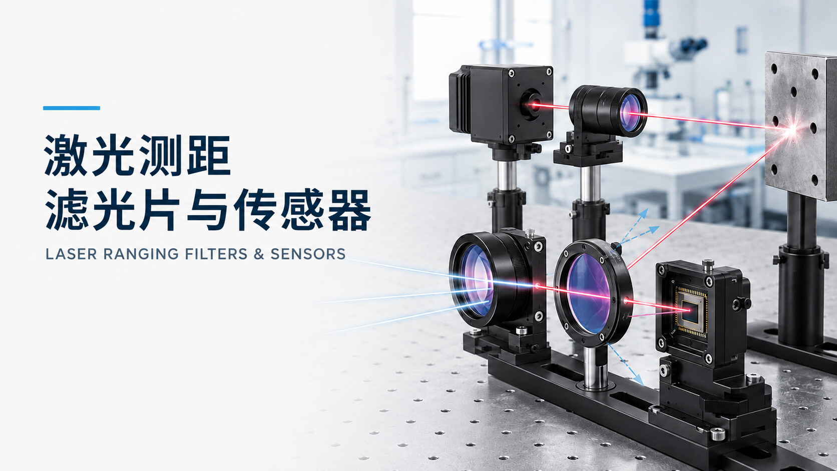
Matching a laser ranging filter to a sensor means preserving as much useful target-return energy as practical while reducing unwanted light from sunlight, artificial illumination, nearby infrared sources, and internal reflections. The filter performs spectral selection, while the detector converts received photons into an electrical signal. Both must be evaluated together with the source and the complete optical path.
Common ranging architectures include direct time of flight, indirect time of flight or phase-based ranging, and triangulation. Their distance calculations differ, but a typical system includes a source, transmitting optics, target reflection, receiving optics, a spectral filter, a photodetector, and signal-processing electronics.
For engineering selection, specifying only a nominal laser wavelength is not enough. The supplier may also need the source linewidth, wavelength tolerance and thermal drift, detector responsivity, receiver field of view, incidence-angle range, ambient-light conditions, filter location, and mechanical tolerances.
Some ranging modules already include an integrated filtering structure. If an external cover window or additional filter is required, its transmission, reflection, scatter, air gap, and transmitter-to-receiver crosstalk should be evaluated at the system level rather than by simply stacking another optical element.
A receiver filter selects wavelengths entering the detector. Under defined conditions, it can improve the ratio of useful return signal to background light, but it does not increase emitted laser power and cannot by itself guarantee outdoor range or measurement accuracy.
Why Does the Filter Affect the Optical System?
Filter selection affects useful return energy, background noise, stray light, receiver field of view, and assembly consistency. Final ranging performance still depends on emitted power, target reflectance and geometry, distance, receiver aperture, detector behavior, electronics, algorithms, and operating environment.
If the filter passband does not cover the source spectrum under actual working conditions, part of the desired return may be attenuated. This is especially important when the source has measurable linewidth, lot variation, or wavelength drift over temperature.
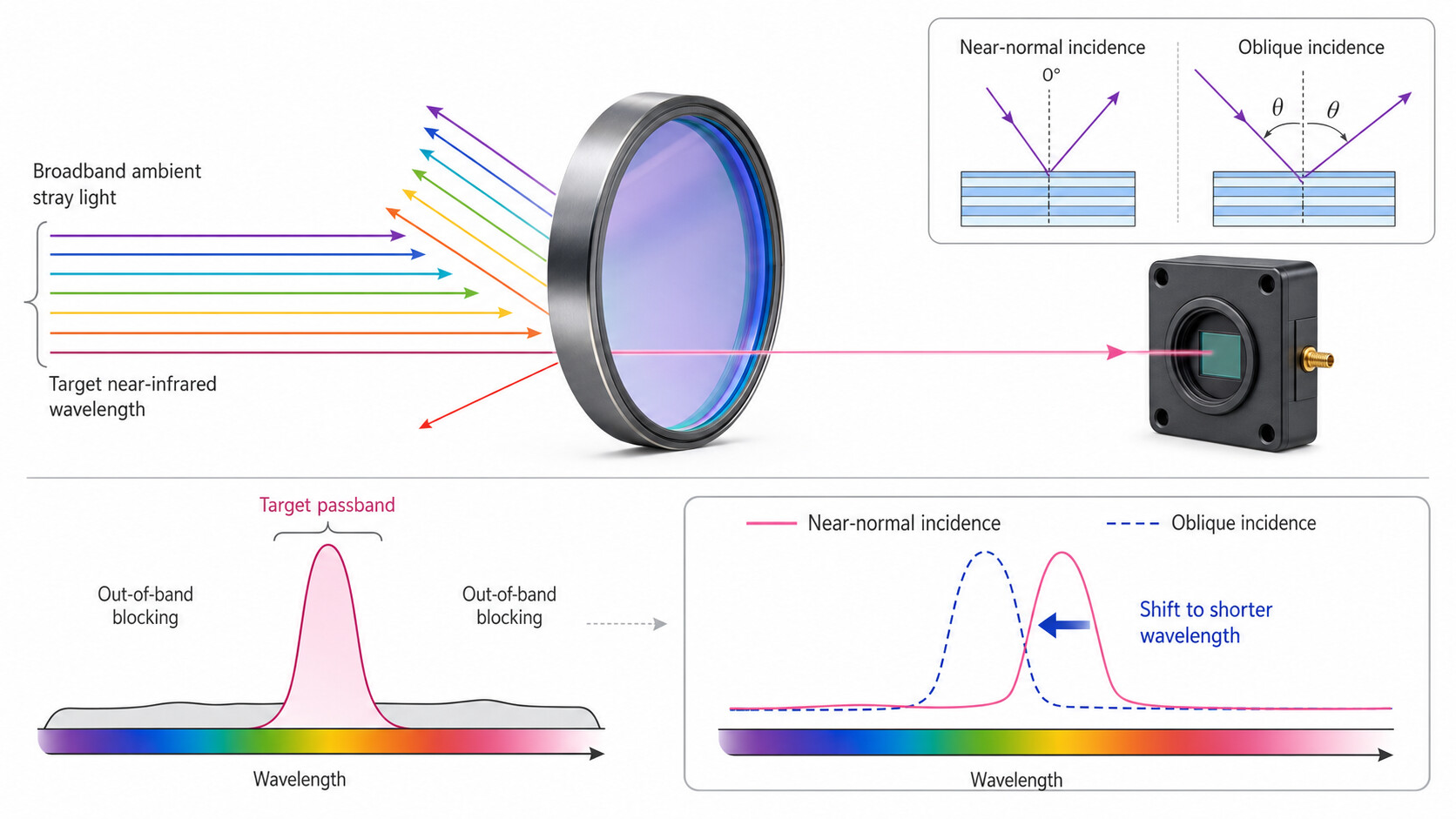
A wider passband can admit more ambient light. Sunlight, artificial lighting, infrared illuminators, and nearby active optical devices may all contribute background within the detector response range. A filter can reject out-of-band energy, but it cannot remove interference that falls inside its transmission band.
For an interference filter, increasing the angle of incidence generally shifts spectral features toward shorter wavelengths and may change the passband shape. In a wide-field or converging beam, center and marginal rays reach the filter at different angles, potentially shifting or broadening the effective system passband.
Cover-window thickness, air gap, tilt, surface reflections, and optical barriers between the transmitter and receiver may also affect crosstalk. A filter that meets its standalone spectral specification still requires validation in the assembled optical and mechanical system.
How Should the Key Parameters Be Evaluated?
The specification should answer four questions: Does the desired return pass through? Are important interference bands blocked? Does the filter work across the real angular distribution? Can the part be manufactured and assembled within the required tolerances? CWL, FWHM, and transmission are only the starting points.
| Parameter | Engineering meaning | What to confirm |
|---|---|---|
| Operating wavelength | Actual emission band of the source | Nominal wavelength, linewidth, tolerance, thermal drift, and expected lot variation |
| Center wavelength (CWL) | Describes the center position of a passband | For many bandpass specifications, CWL is the midpoint between the two half-maximum edge wavelengths; the exact definition should be stated |
| Full width at half maximum (FWHM) | Width between the two half-maximum edges | Wide enough to cover the required return band, but controlled to limit unwanted background |
| Passband transmission | Transmission within the useful spectral band | Whether the requirement is peak, average, or absolute minimum transmission |
| Out-of-band blocking | Attenuation outside the desired passband | Blocking wavelength range and required level across detector-sensitive regions |
| Optical density (OD) | Logarithmic representation of attenuation | With transmittance T expressed from 0 to 1, OD = −log10(T); OD4 corresponds to 0.01% transmission |
| Angle of incidence (AOI) | Angle between the incident ray and the surface normal | Nominal angle, permitted range, receiver field of view, and cone angle—not only a 0° curve |
| Polarization | Polarization state of the incident light | At larger AOI, evaluate possible differences between S and P polarization |
| Substrate | Material supporting the optical coating | Spectral compatibility, thickness, thermal behavior, and mechanical requirements |
| Clear aperture | Area available for the working optical beam | Relationship to external size, mounting edge, bevels, field of view, and assembly tolerance |
| Surface quality | Permitted scratches, digs, and other defects | Set according to imaging, energy collection, reliability, and cost requirements |
| Flatness and transmitted wavefront | Effect on beam or image quality | More important in imaging paths; avoid unnecessarily tight limits in a non-imaging receiver |
| Wedge and parallelism | Angular relationship between the two surfaces | Important when controlling ghost reflections, return light, or installation direction |
| Mechanical tolerances | Diameter, length, width, and thickness requirements | Compatibility with barrels, holders, adhesive bonding, retaining rings, and position tolerances |
| Environmental conditions | Temperature, humidity, contamination, and cleaning exposure | Select substrate, coating, and validation methods for the real use environment |
Spectral inspection should define the measured wavelength range, AOI, beam position, polarization condition, and whether peak, average, or absolute criteria apply. For deep blocking requirements, the measurement system must have sufficient dynamic range and stray-light control to support the claimed OD.
Dimensions, cosmetics, surface quality, flatness, and wedge may be inspected against the drawing. Large apertures, narrow passbands, wide angular ranges, and imaging applications may justify multi-position spectral tests, measurements at actual AOI, or transmitted-wavefront evaluation.
Common Applications
Laser ranging filters are used where an active optical return must be extracted from a more complex background. Requirements vary significantly with wavelength, field of view, package size, target behavior, ambient illumination, and operating environment.
Machine Vision and 3D Sensing
Used in depth sensing, object positioning, dimensional assessment, gesture sensing, and automation guidance. Field of view, imaging quality, and sensor-window integration may be as important as the nominal spectrum.
Industrial Ranging and Inspection
Used for position feedback, level sensing, robotic obstacle detection, logistics equipment, and automated production. Target reflectance, dust, illumination, and installation distance should be tested.
LiDAR and Scanning Systems
Used to isolate the intended laser-return band. Scanning angle, receiver field of view, ambient light, and detector response can change the practical filter requirement.
Consumer and Smart Devices
Used in proximity sensing, focus assistance, gesture recognition, and spatial sensing. Miniaturization, cover appearance, transmitter-receiver isolation, and air gap are frequent integration considerations.
Infrared Sensing and Security
A filter can select the target band used by an infrared source and detector. Detection distance and recognition performance still depend on the source, optics, detector, electronics, and algorithms.
Research and Medical Equipment
Filters may provide wavelength selection and background suppression in optical ranging, positioning, or sensing modules. A filter specification alone cannot establish medical effectiveness or final-device accuracy.
Depending on the source band, detector response, and blocking requirement, an engineering team may evaluate narrow bandpass filters, bandpass filters, or infrared filters.
What Information Is Needed for Selection or Customization?
A useful inquiry should include optical, mechanical, environmental, and inspection requirements. Data that reflects the real operating condition helps determine whether an existing filter is suitable or a custom coating and substrate configuration should be evaluated.
- Define the ranging method and use case, such as direct ToF, indirect ToF, phase-based ranging, triangulation, or another architecture.
- Confirm the source wavelength, linewidth, wavelength tolerance, thermal drift, and operating-temperature range.
- Confirm the detector response, receiver field of view, lens f-number, or beam cone.
- Use the detector response and ambient spectrum to define the passband, blocking range, and target OD.
- Confirm the installation position, incident direction, size, thickness, air gap, and optical-isolation structure.
- Validate samples under representative ambient light, target reflectance, distance, and temperature conditions.
- After sample approval, define production inspection items, sampling rules, and spectral-data requirements.
RFQ and Customization Checklist
- Application and ranging architecture
- Source type, target band, and applicable laser-safety requirements
- Laser CWL, linewidth, wavelength tolerance, and thermal drift
- Sensor model or detector responsivity curve
- Required CWL, FWHM, and passband transmission
- Blocking wavelength ranges and OD levels by region
- Nominal AOI, angular range, receiver field of view, or cone angle
- External dimensions, thickness, and clear aperture
- Substrate, surface quality, flatness, parallelism, or wedge
- Temperature, humidity, contamination, cleaning, and abrasion conditions
- Mounting method, air gap, coated-surface direction, and assembly tolerances
- Prototype quantity, expected production volume, and lot-consistency requirements
- Spectral, dimensional, cosmetic, or transmitted-wavefront inspection requirements
- Availability of a 2D drawing, 3D assembly, reference sample, or sensor documentation
If the filter also functions as an external cover, specify its appearance, surface treatment, exclusion zones, air gap, and transmitter-receiver isolation. The mechanical and optical requirements may also be reviewed together with optical windows or optical lenses.
What Determines Price, Performance, and Lead Time?
Price and solution differences usually depend on spectral difficulty, substrate, dimensions, tolerances, coating design, inspection requirements, and quantity. A nominal wavelength alone is not enough for a meaningful quotation or technical comparison.
- Passband width and CWL tolerance
- Peak, average, or absolute minimum transmission
- Blocking range, blocking depth, and segmented OD requirements
- AOI, cone angle, and polarization conditions
- Substrate, external dimensions, thickness, and clear aperture
- Surface quality, flatness, parallelism, and wedge
- Number of coated surfaces and any antireflection requirement on the opposite surface
- Environmental durability, cleaning, and handling requirements
- Single-point, multi-position, or multi-angle spectral inspection
- Prototype quantity, validation stage, and expected production volume
A narrower passband, deeper blocking over a wider spectral range, or tighter angular performance can increase design, manufacturing, and inspection difficulty. Higher numerical specifications are not automatically better; the appropriate solution balances useful return energy, background suppression, angular shift, manufacturability, and project cost.
Lead time usually depends on substrate availability, coating complexity, dimensional processing, sample validation, inspection scope, and quantity. It should be confirmed after the optical and mechanical requirements have been reviewed.
Common Selection Mistakes
Most filter-selection errors come from treating one nominal value as a complete system specification. Source, detector, filter, receiver optics, mechanics, ambient conditions, and signal processing should be reviewed together.
Correct view: A narrow passband can reduce part of the background, but it can also attenuate the useful return if it does not cover source linewidth, thermal drift, manufacturing tolerance, and angular shift.
Correct view: The system must also account for source tolerance, operating temperature, filter AOI, beam cone, polarization, and coating-production tolerance.
Correct view: OD must be tied to a defined blocking range. An OD value without wavelength limits does not show whether interference is controlled across the detector-sensitive spectrum.
Correct view: Peak transmission is a single-point value. Review average or absolute passband transmission, passband shape, source overlap, and performance at actual incidence angles.
Correct view: A receiver filter performs spectral selection and background suppression. It does not increase emitted power and cannot independently guarantee range, penetration, or accuracy.
Correct view: Validate system crosstalk, target behavior, ambient light, temperature, contamination, assembly variation, and lot-to-lot spectral consistency.
Correct view: Compatibility depends on the actual source spectrum, complete filter curve, detector response, AOI, and operating conditions. Similar-looking filters may not be spectrally interchangeable.
GIAI Photonics Products and Custom Support
GIAI Photonics can review wavelength, bandwidth, out-of-band blocking, AOI, substrate, dimensions, and integration requirements for laser ranging filters, cover windows, and related precision optical components. Final specifications should be based on the drawing, agreed spectral criteria, and system-level validation.
For wavelength-selective receiver paths, review narrow bandpass filters, bandpass filters, and infrared filters. Broader custom options can be discussed through the optical filters product category.
Where the component must also protect the sensor or fit into an imaging assembly, the filter may be evaluated with optical windows or optical lenses. A practical development sequence is specification review, drawing confirmation, prototype inspection, system testing, and production acceptance criteria.
Technical Content Note
This page is written from the perspective of optical filter, coating, window, lens, and precision-component selection. Final requirements should be based on the actual wavelength, bandwidth, transmission, OD, dimensions, substrate, coating curve, drawing, and inspection criteria.
For medical equipment, laser systems, infrared sensing, machine vision, or research instruments, qualified engineering personnel should review the source, receiver optics, detector, mechanical assembly, signal processing, and complete system configuration.
Frequently Asked Questions
Laser ranging filter selection depends on the combined match among wavelength, bandwidth, blocking, AOI, detector response, and mechanical integration. The following answers support engineering review and RFQ preparation.
Does every laser ranging sensor need a separate optical filter?
Not necessarily. Some sensor modules already include spectral filtering, while other systems need a separate receiver filter or filtered cover window. The decision should be based on module documentation, ambient-light conditions, cover design, and assembled-system crosstalk testing.
Is a narrower laser ranging filter always better?
No. A narrower passband can reduce part of the background, but it must still cover source linewidth, wavelength tolerance, thermal drift, filter manufacturing tolerance, and AOI-related shift. If it is too narrow, the useful return may be attenuated at temperature or field-angle extremes.
How should the filter CWL be matched to the laser?
Use the source spectrum across its full operating-temperature and production range rather than only its room-temperature nominal wavelength. Include filter AOI, converging-beam geometry, polarization, and coating tolerance so the target band remains inside the passband under worst-case conditions.
What OD is required for a laser ranging filter?
There is no universal OD value. The requirement depends on ambient interference, detector responsivity, permitted background level, and signal-processing design. Specify both the OD level and its wavelength range, and state whether the criterion is average or absolute across that range.
Can filters for different ranging wavelengths be substituted?
Usually not without verification. Each filter passband and blocking design should match the corresponding source and detector. Even when a detector responds at both wavelengths, the filter may strongly attenuate the alternate source. Review complete spectra at the actual AOI and temperature.
What inspection data should be requested?
Depending on the project stage, request CWL, FWHM, passband transmission, blocking, and dimensional results. State whether you need a typical curve, an individual measured curve, or lot-sampling data. Wide-angle, narrowband, or imaging applications may need multi-angle, multi-position, cosmetic, or wavefront testing.
Why should filters not be compared by unit price alone?
Quotations may represent different substrates, passband tolerances, blocking ranges, OD levels, dimensions, surface requirements, and inspection methods. Align the drawing, spectral acceptance criteria, quantity, and documentation before comparing prototype and production costs.
Should samples be validated before production?
Yes. A passing standalone spectrum confirms only the agreed filter measurement. The assembled system may still be affected by target reflectance, ambient light, cover reflections, transmitter-receiver crosstalk, temperature, contamination, and alignment. Validate representative samples before finalizing production tolerances.
Discuss a Custom Laser Ranging Filter
For a laser ranging, ToF sensing, infrared sensing, machine vision, or precision-inspection project, prepare the operating wavelength, passband, blocking range, AOI, dimensions, substrate, quantity, drawing, and inspection requirements for technical review.
Contact GIAI Photonics