
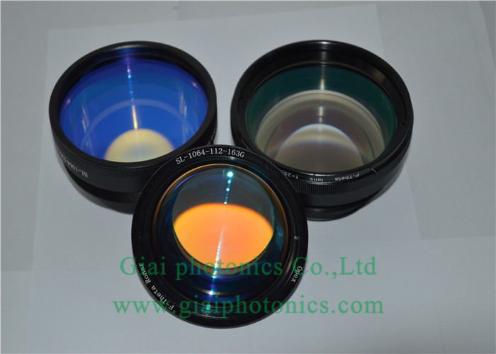
1064nm F Theta Lens Manufacturer
A technical guide to 1064nm F-theta scan lenses for galvanometer-based laser marking, engraving, drilling, cutting, welding, cleaning and precision material-processing systems.
Quick Answer
A 1064nm F-theta scan lens is a multi-element focusing objective designed for a laser scanning system operating at or near 1064 nm. When installed after an XY galvanometer scanner, the lens focuses the deflected beam onto a substantially flat working plane and creates an approximately linear relationship between optical scan angle and focal position. Selecting a suitable lens requires more than wavelength matching. The effective focal length, input beam diameter, scanner aperture, mirror spacing, scan field, working distance, beam quality, pulse conditions, coating design and mechanical interface must all be evaluated as one optical system.
What Is a 1064nm F-Theta Scan Lens?
An F-theta lens, also called a scan lens, plane-field objective or flat-field scanning objective, is designed to focus a moving laser beam across a substantially flat image field.
A conventional focusing lens normally forms its best focal surface on a curved field. That behavior is unsuitable for many galvanometer-based laser systems because the workpiece is usually positioned on a flat table or fixture. An F-theta lens uses a multi-element optical design to reduce field curvature and control off-axis aberrations as the beam moves away from the optical axis.
The term 1064nm F-theta lens indicates that the optical design and anti-reflection coating are intended for a laser wavelength or wavelength band around 1064 nm. This wavelength is commonly associated with Nd:YAG, Nd:YVO4 and many ytterbium-doped fiber laser systems.
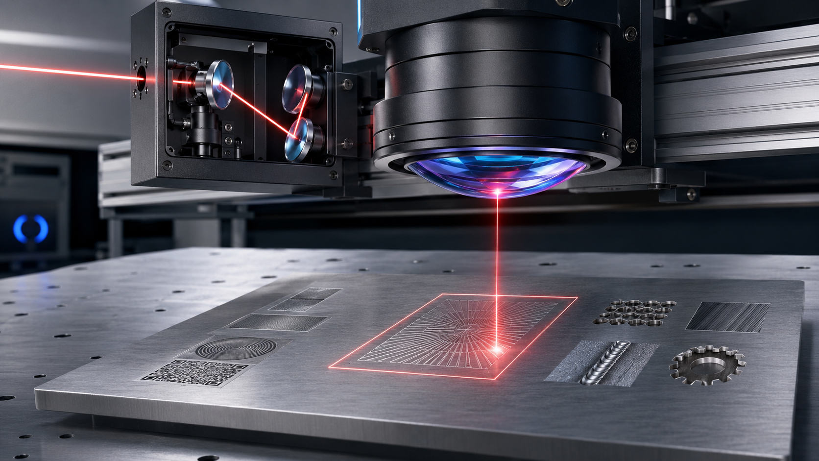
How an F-Theta Lens Works with a Galvanometer Scanner
A two-axis galvanometer scanner normally uses two rotating mirrors. One mirror deflects the beam in the X direction and the second mirror deflects it in the Y direction. After leaving the scan head, the beam enters the F-theta lens and is focused at a corresponding location on the workpiece.
In an ideal one-axis F-theta system, focal position is approximately proportional to effective focal length and optical scan angle:
Here, y is the focal position or image height, f is the effective focal length and θ is the optical scan angle expressed in radians.
This is an idealized one-dimensional relationship. In a real two-axis scan head, the final X and Y coordinates are also affected by the separation of the two galvanometer mirrors, lens position, scan-head geometry, residual F-theta distortion, mirror response, mounting alignment and calibration data.
Optical scan angle versus mechanical mirror angle
The optical scan angle describes the angular deflection of the laser beam entering the scan lens. The mechanical mirror angle describes the physical rotation of the galvanometer mirror.
For reflection from a rotating mirror, the optical deflection is approximately twice the mechanical mirror rotation. Lens and scan head datasheets must therefore be checked carefully to determine which angle is being specified.
Typical Applications of 1064nm F-Theta Lenses
A 1064nm scan lens can be considered for continuous-wave or pulsed laser systems. Pulsed sources may use Q-switched or MOPA architectures and may operate in nanosecond, picosecond or femtosecond regimes. The lens design and coating must be assessed for the actual laser conditions.
| Application | Typical Process Objective | Important Lens Considerations |
|---|---|---|
| Laser marking | Produce text, codes, logos, traceability marks or controlled surface contrast. | Scan field, spot consistency, distortion, marking resolution, working distance and calibration. |
| Laser engraving | Remove material to create depth, texture or permanent graphical features. | Focused spot, depth of focus, field uniformity, coating durability and process energy density. |
| Laser drilling | Produce holes, vias or microfeatures through controlled localized ablation. | Small spot, image-side telecentricity, beam quality, pulse compatibility and positioning stability. |
| Laser cutting | Separate, trim or contour thin materials and selected industrial components. | Spot size, working distance, incidence angle, scan-field edge performance and process clearance. |
| Laser welding | Deliver controlled energy along a joint or programmed weld path. | Average power, thermal focus shift, spot stability, back reflections, cooling and contamination control. |
| Laser cleaning | Remove oxides, coatings, residues or contaminants from a selected surface. | Large-area scanning, overlap control, energy uniformity, coating absorption and thermal stability. |
| Precision micromachining | Texture, trim, ablate or modify small features and localized functional structures. | Low aberration, stable spot geometry, pulse bandwidth, field calibration and application-specific telecentricity. |
The presence of an application in this table does not mean that one lens can be used interchangeably for marking, welding, drilling and cleaning. These processes can have very different spot, power, pulse, telecentricity and thermal requirements.
Key Specifications Buyers Should Evaluate
| Parameter | Technical Meaning | Why It Matters |
|---|---|---|
| Design wavelength | Wavelength or wavelength band used for optical optimization and coating design. | Influences transmission, aberration correction, absorption, thermal behavior and reflection loss. |
| Effective focal length | Optical focal length measured from the principal plane of the assembled lens system. | Strongly influences scan field, focused spot size, depth of focus and system dimensions. |
| Scan field | Specified usable processing area under defined scanner geometry and beam conditions. | Determines whether the lens covers the required workpiece while maintaining acceptable optical performance. |
| Input beam diameter | Laser beam diameter entering the scanner or scan lens, normally defined at the 1/e² intensity points. | Affects focused spot size, clipping, diffraction, fluence and scanner-aperture requirements. |
| Scanner aperture | Clear optical aperture of the galvo scan head. | Must accommodate the beam throughout the required mirror positions without unacceptable vignetting. |
| Mirror spacing | Axial separation and geometrical relationship between the X and Y galvanometer mirrors. | Influences field size, vignetting, lens position, telecentricity and calibration. |
| Working distance | Distance from a defined mechanical reference on the lens housing to the nominal working plane. | Determines machine clearance, fixture space, enclosure design and protective-window placement. |
| Focused spot diameter | Beam-waist diameter under specified wavelength, M², beam diameter and aperture conditions. | Influences achievable energy density and potential feature size, but is not identical to process line width. |
| Optical scan angle | Maximum beam angle accepted by the lens for the stated performance and vignetting conditions. | Works with focal length to determine the practical scan field. |
| F-theta distortion | Deviation from the ideal linear fθ mapping relationship. | Influences geometric accuracy and the correction required from the scanner controller. |
| Image-side telecentricity | Degree to which chief rays remain perpendicular to the work plane across the field. | Important for angle-sensitive features, vertical walls, drilling and consistent edge geometry. |
| Optical materials | Glass or fused-silica materials used for the lens elements. | Affects absorption, thermal expansion, refractive index, pulse suitability and manufacturability. |
| AR coating | Anti-reflection coating designed for the operating wavelength and incidence-angle range. | Reduces surface reflection, unwanted return energy and absorption-related thermal effects. |
| Laser operating conditions | Average power, pulse energy, pulse duration, repetition rate, duty cycle and beam profile. | Required to assess thermal loading, peak fluence, coating damage risk and long-term stability. |
| LIDT | Laser-induced damage threshold measured under defined wavelength, pulse and beam conditions. | Cannot be treated as a universal maximum-power rating. Test conditions must match the intended application. |
| Mechanical interface | Housing diameter, thread, flange, mounting surface and reference dimensions. | Determines physical compatibility with the scan head and machine assembly. |
Focal Length, Scan Field and Spot Size Trade-Offs
Effective focal length is one of the most important decisions in F-theta lens selection. It affects the size of the usable processing field, working distance, focused spot and overall system layout.
Shorter focal length
A shorter focal length generally supports a smaller focused spot and a more compact optical layout. It usually produces a smaller scan field and shorter working distance.
Longer focal length
A longer focal length can support a larger processing field and greater mechanical clearance. With other variables unchanged, it also produces a larger diffraction-related spot.
For a Gaussian-like beam, the focused 1/e² spot diameter may be approximated by:
d is the focused 1/e² diameter, M² is the beam-quality factor, k is a correction factor related to aperture and beam diameter, λ is wavelength, f is focal length and D is the input beam diameter.
The equation is useful for preliminary comparison, but it is not a guarantee of the final processing feature size. Real spot shape and diameter also depend on beam profile, truncation, lens aberrations, field position, alignment, contamination, focus setting and thermal effects.
Why the Beam Expander and Scanner Aperture Matter
A beam expander increases the diameter of the collimated laser beam before it reaches the galvanometer scanner. Under suitable conditions, increasing the beam diameter can reduce the theoretical focused spot size.
However, the expanded beam must fit through the complete scan path. If the beam approaches or exceeds the scanner aperture, it may be clipped at certain mirror positions. Beam clipping can cause:
- Reduced transmitted power
- Asymmetric or distorted focal spots
- Increased diffraction
- Different edge and center performance
- Inconsistent process energy across the scan field
Beam-expander magnification should therefore be selected together with the laser beam diameter, galvanometer aperture, mirror size, lens entrance pupil and target spot requirement.
Working Distance Is Not the Same as Focal Length
Effective focal length is an optical property measured from the principal plane of the complete lens system. Working distance is a mechanical installation distance measured from a specified point on the lens or housing to the designed focal plane.
Depending on the supplier, a drawing may refer to working distance, free working distance, back focal length or another mechanical reference. These dimensions should not be assumed to be interchangeable.
Working distance affects:
- Workpiece and fixture clearance
- Fume-extraction positioning
- Protective-window installation
- Collision risk
- Machine-enclosure design
- Focus adjustment and calibration access
Buyers should request a mechanical drawing showing the exact reference surface used for the working-distance specification.
F-Theta Distortion and System Calibration
An F-theta lens is intentionally designed to create a mapping close to y = fθ. In practice, the mapping is not perfectly linear at every point in the scan field.
Residual coordinate error can arise from:
- Lens-design residual distortion
- Galvanometer mirror spacing
- Scanner angular response
- Lens-to-scanner mounting distance
- Mechanical alignment
- Controller scaling
- Temperature-dependent drift
- Manufacturing and assembly tolerances
A correction file or calibration table can compensate for predictable system-level errors. Calibration should be performed with the actual lens, scanner, controller, mounting geometry and working plane.
A low nominal lens-distortion value does not eliminate the need for system calibration.
Standard and Telecentric F-Theta Lenses
In a non-telecentric scan lens, the chief-ray angle normally increases toward the edge of the scan field. In an image-side telecentric design, the focused beam reaches the work plane more nearly perpendicular across the usable field.
A low telecentricity error may be useful when:
- Drilled holes should remain close to vertical
- Cut-wall angle must be controlled
- Feature geometry is sensitive to beam-incidence angle
- Center and edge processing must be more consistent
- The workpiece contains recessed or depth-sensitive structures
Telecentricity is not automatically required for every marking or engraving application. Telecentric designs usually need larger front optics and may provide a smaller practical field than a comparable non-telecentric design.
Optical Materials, Coatings and Back Reflections
Optical material and coating selection should be based on the complete laser and process specification.
Optical material
Fused silica may be considered for demanding high-power or short-pulse applications because of its relatively low absorption and low thermal expansion. Other optical-glass combinations may be suitable when field size, aberration correction, cost, element size or mechanical requirements are different.
Anti-reflection coating
The coating should be optimized for the operating wavelength and angle range inside the lens. A coating described only as “near-IR” may not provide the same performance as a coating designed specifically around 1064 nm.
Ghost reflections
A portion of the laser energy can reflect from optical surfaces and form internal or external ghost foci. Under high-power or short-pulse conditions, these reflections may damage lens elements, protective windows, scanner mirrors or upstream components.
For demanding applications, the optical review should include back-reflection positions, internal ghost behavior, coating absorption and the location of nearby scanner mirrors.
Laser Power and Damage-Threshold Assessment
A single statement such as “high-power compatible” is not sufficient for technical approval.
Continuous-wave lasers
Average power, beam diameter, coating absorption, thermal conductivity, mounting and cooling influence heating, thermal focus shift and long-term stability.
Pulsed lasers
Pulse energy, pulse duration, repetition rate, beam area, peak intensity and fluence influence coating and bulk-material damage risk.
Laser-induced damage threshold values are meaningful only when the measurement conditions are stated. A threshold measured at one wavelength, pulse duration, repetition rate or beam size cannot be directly treated as a universal maximum operating power.
For a technical review, provide:
- Nominal wavelength and spectral bandwidth
- Continuous-wave or pulsed operation
- Average laser power
- Maximum pulse energy
- Pulse duration
- Repetition rate
- Beam diameter and definition method
- Beam-quality factor or M²
- Beam profile and polarization
- Expected duty cycle
- Potential back-reflection conditions
- Environmental and contamination conditions
1064nm F-Theta Lens Selection Checklist
Supplying complete system information helps an optical manufacturer determine whether an existing design can be evaluated or whether a customized lens is required.
- Laser wavelength and wavelength tolerance
- Laser architecture and operating mode
- Average power and peak power
- Pulse energy, duration and repetition rate
- Input beam diameter at the scanner
- M² or beam parameter product
- Galvanometer clear aperture
- X and Y mirror spacing
- Lens-to-scanner mounting distance
- Required rectangular or circular scan field
- Preferred effective focal length
- Required working distance
- Target focal spot diameter
- Maximum acceptable F-theta distortion
- Telecentricity requirement
- Workpiece material and process type
- Target feature size and accuracy
- Housing diameter, thread or flange
- Protective-window requirement
- Prototype and expected production quantity
When Is a Custom 1064nm F-Theta Lens Required?
A customized F-theta lens may be considered when a standard lens cannot satisfy the required combination of wavelength, field size, focal length, aperture, working distance, telecentricity, power conditions or mechanical integration.
Project-specific variables may include:
- Effective focal length and working distance
- Rectangular, square or circular scan field
- Input beam diameter and entrance aperture
- Optimization for a specific galvo mirror spacing
- Optical and mechanical scan-angle range
- Image-side telecentricity target
- Optical-glass or fused-silica configuration
- 1064nm AR coating design
- Low-absorption or short-pulse coating requirements
- Back-reflection and ghost-focus control
- Housing dimensions and mounting thread
- Protective-window and environmental requirements
Changing the scanner, beam diameter, mirror spacing or mounting position can change the practical scan field, spot diameter, vignetting and telecentricity. A customized scan lens should therefore be evaluated as part of the complete optical system.
Quality Inspection and Documentation
The inspection plan should be based on the approved drawing and application requirements. Not every project requires every test, and no tolerance should be assumed without written confirmation.
| Inspection Area | Possible Verification Items |
|---|---|
| Optical materials | Material grade, refractive-index data, homogeneity or other project-specific material requirements. |
| Lens elements | Surface quality, surface figure, center thickness, wedge, centration and clear aperture. |
| Coating | Spectral transmission or reflection under the approved wavelength and angle conditions. |
| Assembled optics | Effective focal length, working distance, transmitted wavefront or other defined assembly performance. |
| Scan-field performance | F-theta distortion, field curvature, focal spot at selected positions and telecentricity error where required. |
| Mechanical assembly | Housing dimensions, thread, flange, runout, reference surfaces and mounting compatibility. |
| Power-related evaluation | Coating absorption, thermal behavior, cleanliness, LIDT data or application-specific testing when agreed. |
Scan-field measurements should define the test wavelength, beam diameter, beam quality, scanner geometry, lens position and measurement criterion. A spot value without its test conditions is not sufficient for system comparison.
Common Purchasing Mistakes
Frequently Asked Questions
What does F-theta mean?
It refers to the designed relationship between focal position and optical scan angle. In an ideal one-axis system, image height is approximately equal to effective focal length multiplied by scan angle: y ≈ fθ.
Can one 1064nm F-theta lens work with every 1064 nm laser?
No. The lens must also match the laser power, pulse conditions, beam diameter, beam quality, scanner aperture, mirror spacing, scan field and mechanical interface.
Does a longer focal length provide a larger scan field?
It often supports a larger field for a given scan angle, but the usable area is also limited by aperture, mirror spacing, vignetting, lens design and acceptable edge performance.
Does a longer focal length produce a smaller spot?
Generally no. With wavelength, beam quality and beam diameter unchanged, increasing focal length increases the diffraction-related focal spot.
Can a beam expander reduce the focused spot?
Increasing the input beam diameter can reduce the theoretical spot size, provided the expanded beam fits through the scanner and lens without unacceptable clipping.
What is the difference between working distance and EFL?
Effective focal length is measured from the optical principal plane. Working distance is measured from a defined mechanical lens reference to the work plane.
When is a telecentric F-theta lens useful?
It may be useful when the beam should strike the work plane more nearly perpendicular across the field, such as for drilling, depth structuring or angle-sensitive processing.
Is calibration still required with a low-distortion lens?
Yes. Calibration compensates for the combined behavior of the lens, galvo scanner, controller, alignment and machine structure.
Can the same lens be used for marking and welding?
It may be possible in a specific system, but it should not be assumed. Welding can require substantially different power, thermal, spot and back-reflection performance.
What information is required for a custom quotation?
Provide the wavelength, laser power and pulse data, beam diameter, M², galvo aperture, mirror spacing, field size, working distance, target spot, telecentricity requirement, mechanical interface and application.
Discuss Your 1064nm F-Theta Lens Requirements with GIAI Photonics
GIAI Photonics manufactures precision optical components and lists F-theta scan lenses within its optical-lens portfolio. Custom optical components can be evaluated according to customer drawings and confirmed project parameters.
To support an efficient technical review, include:
- Laser wavelength and operating mode
- Average power and pulse parameters
- Input beam diameter and M²
- Galvo aperture and mirror spacing
- Required scan field and working distance
- Target spot and telecentricity requirement
- Mechanical drawing or mounting dimensions
- Workpiece material and intended process
All optical, mechanical, coating, transmission, distortion, spot-size, power-handling and delivery specifications require project-specific confirmation. No unconfirmed catalog value or performance tolerance is implied by this article.