

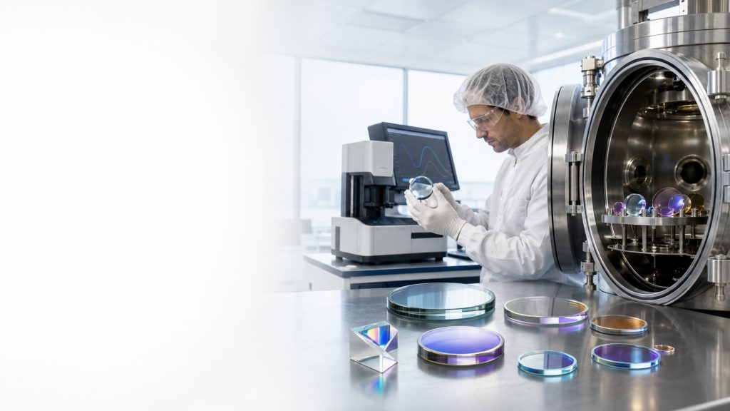
An anti reflection coating manufacturer designs and deposits thin-film layers that reduce unwanted surface reflection from lenses, windows, filters, prisms, and other optical components. Selecting a manufacturer requires more than requesting “high transmission.” The coating must be matched to the operating wavelength, substrate, angle of incidence, polarization, component geometry, environmental conditions, and laser power where applicable. Buyers should also define whether reflectance is measured per surface, across both surfaces, at a single wavelength, or over a complete spectral band. A suitable supplier should be able to review drawings, clarify acceptance criteria, recommend a coating structure, produce samples, and provide inspection data under agreed test conditions. These details determine whether the finished component performs correctly in the actual optical system.
What Is an Anti-Reflection Coating?
Definition: An anti-reflection coating is a single-layer or multilayer thin-film structure applied to an optical surface to reduce reflected light and increase the amount of usable light entering or leaving an optical system.
Reflection occurs wherever light crosses an interface between materials with different refractive indices. A bare optical surface can therefore produce transmission loss, ghost images, stray light, reduced contrast, detector noise, or unwanted laser feedback.
An AR coating uses controlled interference between reflections from different film interfaces. The coating materials, refractive indices, physical thicknesses, and layer sequence are selected so that unwanted reflected waves partially cancel within the specified operating conditions.
AR performance is not universal. A design optimized for one wavelength, incident angle, or substrate may perform differently when any of those conditions change.
How Anti-Reflection Coatings Work
At normal incidence, the approximate Fresnel reflectance of a bare interface can be expressed as:R=(n1+n2n1−n2)2
Here, n1 and n2 are the refractive indices on the two sides of the interface.
A basic single-layer AR design commonly uses an optical thickness of approximately one-quarter of the design wavelength:ncd=4λ0
Where:
- nc is the refractive index of the coating layer
- d is its physical thickness
- λ0 is the design wavelength
This simplified structure can provide low reflection near one wavelength and one angle. Broader wavelength ranges, multiple wavelength bands, oblique incidence, polarization-sensitive systems, and demanding laser applications generally require more complex multilayer designs.
The lowest reflectance value at one wavelength does not describe the complete performance of a coating. Engineers should examine the full spectral curve, angular range, polarization state, substrate absorption, surface count, and measurement conditions.
Main Types of Anti-Reflection Coatings
| Coating Type | Typical Design Goal | Main Advantages | Important Limitations |
|---|---|---|---|
| Single-layer AR | Reduce reflection near one design wavelength | Simple structure and suitable for defined operating conditions | Limited bandwidth and angular tolerance |
| Single-wavelength multilayer AR | Achieve very low reflection around a laser or source wavelength | Optimized performance in a narrow operating region | Sensitive to wavelength, AOI, and process tolerances |
| Broadband AR | Reduce reflection across a wider spectral range | Useful for imaging, illumination, and multispectral instruments | More complex design and potential performance trade-offs |
| Dual-band or multi-band AR | Reduce reflection in two or more separated spectral regions | Supports systems using multiple sources or detection bands | Requires clearly defined bands and blocking expectations |
| Wide-angle AR | Maintain controlled reflection over an angular range | Suitable for converging beams or varying field angles | S- and P-polarized responses may separate at oblique incidence |
| Infrared AR | Improve surface transmission in selected infrared bands | Supports thermal imaging, sensing, and infrared lasers | Substrate absorption and environmental exposure require attention |
| High-power laser AR | Reduce reflection and absorption at a laser wavelength | Helps limit loss, heating, and back-reflection | Requires detailed laser parameters and suitable damage testing |
The correct category depends on the complete system. Terms such as “broadband” or “high-power” are not sufficient specifications unless the wavelength limits, acceptance values, test conditions, and use environment are defined.
Parameters to Give an Anti Reflection Coating Manufacturer
A coating request should translate system requirements into measurable optical and mechanical criteria.
1. Operating Wavelength
Specify the actual operating wavelength or wavelength band. For a laser system, include the nominal wavelength and any expected variation. For an imaging system, define the source spectrum, detector response, and spectral region that contributes to the image.
A coating designed for visible imaging will not automatically provide suitable performance in ultraviolet or infrared systems.
2. Reflection Requirement
State whether the requirement applies to:
- Reflectance at one wavelength
- Average reflectance over a band
- Maximum reflectance anywhere within a band
- One coated surface
- Both surfaces of the component
- A specified AOI and polarization
- A witness sample or the completed optical component
Average reflectance can conceal a narrow region with higher reflection. If that region overlaps an important source or detector wavelength, a maximum reflectance limit may also be necessary.
3. Transmission Requirement
High transmission is related to low reflection, but the two are not interchangeable. Finished-component transmission can also be limited by:
- Substrate absorption
- Coating absorption
- Surface scatter
- Bulk material defects
- Adhesives or assembly materials
- Other coated or uncoated surfaces in the optical path
Transmission should therefore be specified across the required wavelength range and under defined measurement conditions.
4. Angle of Incidence
A coating spectrum generally shifts as the angle of incidence changes. The response of S- and P-polarized light can also separate at oblique angles.
Specify:
- Nominal AOI
- Minimum and maximum AOI
- Whether the beam is collimated or converging
- Numerical aperture or cone angle where relevant
- Polarization state
- Whether the component rotates or scans during operation
A normal-incidence spectral curve should not be used to approve a design operating at a substantial oblique angle.
5. Substrate Material
The substrate affects coating design, deposition conditions, adhesion, thermal behavior, transmission range, and manufacturability.
Common substrate categories include:
- Optical crown glass
- Fused silica
- Sapphire
- Calcium fluoride and other crystalline materials
- Silicon
- Germanium
- Zinc selenide
- Specialty infrared materials
The manufacturer should receive the exact substrate designation rather than a general description such as “glass” or “IR material.”
6. Component Geometry
Coating uniformity can be affected by:
- Diameter and thickness
- Clear aperture
- Surface curvature
- Steep lens geometry
- Edge shape and bevels
- Wedges or prisms
- Recessed surfaces
- Mounted components
- Very small or unusually large parts
Curved optical lenses for machine vision may require different fixture and uniformity considerations from flat optical windows for protective assemblies.
7. Polarization
For near-normal incidence, polarization may have a limited effect in many systems. At larger angles, the S- and P-polarized reflection curves can differ significantly.
Define whether the system uses:
- Unpolarized light
- Randomly polarized light
- Linear polarization
- A known S or P orientation
- Changing polarization states
Polarization should be treated as a required input when evaluating scanning, beam steering, dichroic, or laser optical systems.
8. Environmental Stability
The operating and storage environment may affect coating selection. Provide relevant information about:
- Temperature range
- Thermal cycling
- Humidity or condensation
- Abrasion and cleaning frequency
- Salt, chemicals, or industrial contamination
- Vacuum or low-pressure operation
- Outdoor exposure
- Sealing and assembly conditions
Do not request “environmentally durable” without identifying the test method, exposure conditions, acceptance criteria, and whether testing applies to samples or production parts.
9. Surface Quality and Wavefront Requirements
Coating performance must be considered together with the underlying optic. Depending on the application, the drawing may need to define:
- Surface quality
- Surface figure
- Flatness
- Transmitted wavefront
- Reflected wavefront
- Wedge
- Parallelism
- Centering
- Clear aperture
- Cosmetic edge requirements
The coating process should not be evaluated independently from the dimensional and optical tolerances of the finished component.
10. Laser Parameters
For laser applications, wavelength and average power alone are insufficient. The manufacturer may also need:
- Laser type
- Continuous-wave or pulsed operation
- Pulse duration
- Repetition rate
- Pulse energy
- Beam diameter
- Beam profile
- Peak power or energy density
- Incident angle
- Polarization
- Beam focus position
- Expected contamination conditions
Low reflection does not by itself prove that a coating is suitable for a high-power laser. Absorption, defects, surface cleanliness, coating design, and test conditions all influence damage risk.
AR Coating Selection by Application
| Application | Primary Coating Concern | Information to Confirm |
|---|---|---|
| Machine vision | Image contrast, ghost control, broad transmission | Source spectrum, sensor response, AOI range, lens geometry |
| Laser processing | Low loss, back-reflection control, damage resistance | Wavelength, power, pulse data, beam size, AOI, polarization |
| Fluorescence detection | Signal throughput and background control | Excitation band, emission band, detector sensitivity, adjacent filters |
| LiDAR and ranging | Source and receiver efficiency | Laser wavelength, receiver band, AOI, polarization, outdoor environment |
| Medical optical equipment | Repeatable transmission and system compatibility | Wavelengths, sterilization or cleaning exposure, validation and compliance needs |
| Infrared sensing | Substrate transmission and low surface loss | IR band, substrate, temperature, humidity, environmental protection |
| Imaging systems | Color balance, contrast, and angular stability | Full spectral band, field angle, detector response, surface count |
| Beam scanning | AOI variation and polarization behavior | Scan angle, beam path, wavelength, galvo compatibility, coating uniformity |
For scanning laser systems, the coating on F-theta scan lenses must be evaluated with the operating wavelength, beam diameter, field angle, and full scan geometry. For thermal or sensing applications, infrared lenses require a design that accounts for both substrate absorption and surface reflection.
Optical Density and Blocking Requirements
Optical density and blocking are normally filter specifications rather than primary AR coating specifications. However, they become relevant when AR layers are combined with spectral filtering functions.
For example, custom optical filters may require:
- High transmission in a passband
- Controlled reflection at external surfaces
- Blocking outside the passband
- Defined optical density over a specified range
- AOI and polarization limits
- Protection against environmental exposure
In these cases, AR performance and blocking performance should be specified separately. A high passband transmission value does not prove that the required out-of-band blocking has been achieved.
How to Choose an Anti Reflection Coating Manufacturer
A capable manufacturer should be evaluated on engineering communication, process control, inspection capability, and production consistency—not only on a quoted reflectance value.
Step 1: Confirm the Manufacturer Understands the System
The supplier should ask about the actual application, not just the component diameter and wavelength. Important questions include where the optic is located, how light reaches it, whether the beam converges, and what failure would affect the system.
Step 2: Review the Coating Specification
The coating requirement should define:
- Wavelength or spectral band
- Reflectance or transmission limit
- AOI and angular range
- Polarization
- Substrate
- Coated surface
- Clear aperture
- Environmental requirements
- Measurement method
- Quantity and production schedule
Ambiguous requirements should be resolved before samples or production parts are made.
Step 3: Evaluate Design and Manufacturing Compatibility
A theoretical design may not be suitable for every substrate, geometry, temperature limit, or production quantity. The manufacturer should evaluate whether the proposed design can be deposited and inspected consistently on the actual component.
Step 4: Define Sample and Approval Requirements
For a new or sensitive application, agree on:
- Prototype quantity
- Sample substrate
- Whether samples use final geometry
- Inspection documentation
- Spectral measurement conditions
- Environmental evaluation
- Dimensional inspection
- Functional testing in the customer’s system
- Criteria for production approval
A coated witness sample can support process monitoring, but it may not represent every property of a curved or unusually shaped production part.
Step 5: Confirm Production Inspection
Ask which requirements will be tested on every lot and which are controlled through process records, sampling, or qualification testing.
The inspection plan may address:
- Spectral performance
- Cosmetic quality
- Coating uniformity
- Dimensions
- Surface figure
- Adhesion or durability
- Packaging and identification
- Lot traceability
Testing scope should be agreed before the order is released.
Typical Custom Coating Workflow
A practical custom project usually follows these stages:
- Application review: The customer provides the operating conditions and system objective.
- Drawing review: Optical, mechanical, coating, and inspection requirements are checked for conflicts.
- Substrate confirmation: Material, grade, geometry, surface preparation, and thermal limitations are reviewed.
- Coating design: A layer structure is developed for the required spectrum, AOI, and polarization.
- Manufacturing assessment: Fixturing, masking, deposition, uniformity, and inspection feasibility are evaluated.
- Sample production: Prototypes or qualification pieces are manufactured when required.
- Optical inspection: Spectral and relevant physical characteristics are measured under agreed conditions.
- Customer evaluation: The part is reviewed in the intended system or against the approval specification.
- Production release: The approved design and inspection criteria are transferred to repeat orders.
Practical Selection Checklist
Before contacting an anti reflection coating manufacturer, prepare the following:
- Application and system function
- Operating wavelength or wavelength band
- Target reflectance and/or transmission
- Average and maximum limits where relevant
- AOI and angular range
- Polarization state
- Substrate material and grade
- Part drawing and revision
- Diameter, thickness, curvature, and clear aperture
- Coated surface identification
- Surface quality and figure requirements
- Environmental and cleaning conditions
- Laser power, pulse, and beam information where applicable
- Inspection and acceptance method
- Prototype and production quantities
- Packaging, handling, and identification requirements
- Sample or existing component for reference
- Target schedule and approval process
Common Mistakes When Ordering AR-Coated Optics
Specifying Only “High Transmission”
This does not define the wavelength range, AOI, substrate, surface count, or measurement method. Transmission can also be limited by substrate absorption rather than reflection.
Using a Single Minimum Reflectance Value
A very low reflectance value at one wavelength may coexist with higher reflection elsewhere. Broadband systems should define the full spectral range and whether both average and maximum limits matter.
Ignoring AOI and Polarization
A design measured at normal incidence may not perform the same way in an oblique or scanning beam. S- and P-polarized responses must be considered where relevant.
Confusing Per-Surface and Finished-Part Performance
A reflectance value may describe one coated interface, while the component contains two or more surfaces. The specification should make this distinction explicit.
Treating All Substrates as Interchangeable
Substrate refractive index, thermal behavior, absorption, and surface condition affect coating design and deposition compatibility.
Requesting a Laser Coating Without Beam Data
Average power does not describe pulse energy, peak intensity, beam size, focus position, or contamination exposure. These details can materially affect the assessment.
Approving Only a Witness Sample
A flat witness sample can be useful for spectral monitoring but may not fully represent coating uniformity or performance on a steeply curved, wedged, or recessed optical surface.
Leaving Inspection Conditions Undefined
Different instruments, incidence angles, apertures, and measurement resolutions can produce different reported results. Acceptance conditions should be agreed before manufacturing.
When to Choose Custom Optical Components
Custom optical components are appropriate when catalog-style coating specifications do not represent the real operating conditions.
Consider customization when:
- The wavelength falls outside standard coating bands
- Two or more separated wavelength regions must be transmitted
- The system operates over a wide AOI range
- S- and P-polarized responses require separate control
- A laser system has demanding loss or damage-risk requirements
- The substrate is infrared, crystalline, unusually thin, or temperature-sensitive
- The part has steep curvature, a recessed surface, or unusual geometry
- AR performance must be combined with spectral filtering
- Environmental or cleaning requirements are application-specific
- Surface figure, wavefront, or dimensional tolerances must be controlled after coating
- A drawing requires coordinated optical fabrication and coating
- Prototype evaluation is necessary before production approval
Custom components may include optical lenses, optical windows, optical mirrors for beam steering, prisms, infrared optics, and filter assemblies. Coordinating substrate fabrication and coating review can help identify tolerance conflicts before production begins.
What to Include in a Request for Quotation
A useful RFQ should include more than a part name and quantity.
Provide:
- Part drawing with revision number
- 3D model when geometry requires it
- Substrate material
- Wavelength range
- Reflectance and transmission requirements
- AOI and polarization
- Surface quality and figure
- Dimensional tolerances
- Environmental requirements
- Laser parameters when applicable
- Inspection and documentation expectations
- Sample quantity
- Production quantity and forecast
- Existing sample or reference spectrum
- Application background
- Known system problem or performance target
If the initial specification is incomplete, identify which parameters are fixed and which can be adjusted. This allows the manufacturer to propose practical coating and tolerance options without assuming requirements that the system does not need.
FAQ
What does an anti reflection coating manufacturer do?
An anti reflection coating manufacturer designs and deposits thin-film layers that reduce unwanted reflection from optical surfaces. The work may include specification review, coating design, substrate preparation, deposition, optical inspection, environmental evaluation, sample production, and production-lot control.
What information does an AR coating manufacturer need?
The supplier normally needs the wavelength range, reflectance or transmission target, AOI, polarization, substrate, part geometry, coated surface, clear aperture, environmental conditions, quantity, and inspection requirements. Laser applications also require beam and pulse information.
What is the difference between single-wavelength and broadband AR coatings?
A single-wavelength coating is optimized around a defined wavelength and operating condition. A broadband coating reduces reflection across a wider spectral range but usually requires a more complex multilayer design and clearly defined performance limits.
Does lower reflection always mean higher transmission?
Not necessarily. Transmission can also be reduced by substrate absorption, coating absorption, scattering, contamination, and losses at other surfaces. Both reflection and finished-component transmission should be evaluated where system throughput is important.
Why must the angle of incidence be specified?
Changing the angle of incidence can shift the spectral response of an AR coating. At oblique angles, S- and P-polarized light may also have different reflection characteristics. The coating should therefore be evaluated at the actual system angle or angular range.
Can the same AR coating be used on different substrate materials?
Not automatically. The substrate refractive index, transmission band, thermal properties, surface condition, and deposition compatibility affect the coating design. A coating should be reviewed for the exact substrate material and component geometry.
How should AR coatings for high-power lasers be specified?
Provide the wavelength, continuous-wave or pulsed operation, average power, pulse duration, repetition rate, pulse energy, beam diameter, beam profile, AOI, polarization, and focus conditions. Damage resistance should be discussed using defined test conditions rather than a general “high-power” description.
Should samples be evaluated before production?
Sample evaluation is advisable for new coating designs, unusual substrates, demanding tolerances, high-power laser systems, or application-specific environmental conditions. The sample plan should define whether testing uses witness pieces, final-geometry components, or both.