
Lens mounting stress affects optical performance by deforming lens surfaces, changing the refractive index inside the material, or shifting the lens from its intended position. These effects can increase wavefront error, move the focal plane, introduce astigmatism or coma, reduce image contrast, alter laser-beam quality, and disturb polarization.
The severity depends on the lens material, diameter, thickness, edge geometry, mounting method, preload, temperature range, adhesive properties, and required optical accuracy. A lens that meets its free-state specification can therefore perform differently after it is installed in a mechanical cell. Experimental studies confirm that clamping stress can affect both transmitted and reflected wavefronts. s Lens Mounting Stress?**
Lens mounting stress is mechanical stress transferred into an optical element by its retaining structure.
The purpose of a mount is to keep the lens centered, axially located, and mechanically secure under gravity, vibration, handling, and temperature changes. However, a mount that applies excessive or uneven force can change the optical element it is intended to protect.
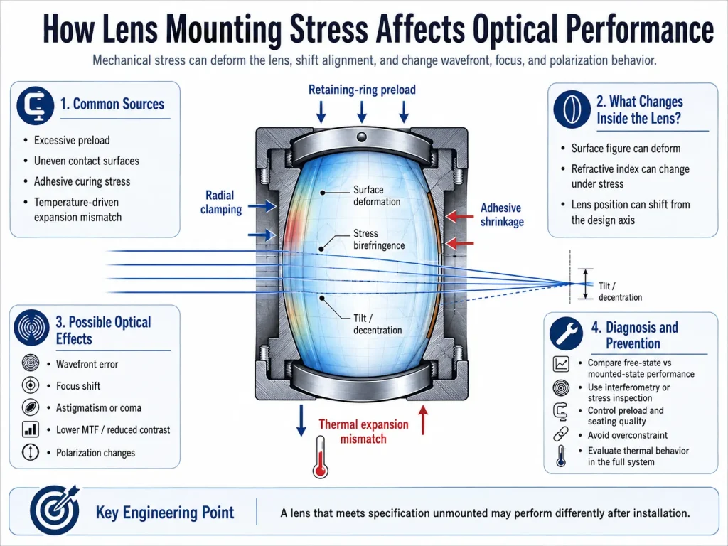
Mounting stress may be introduced by:
- Excessive retaining-ring preload
- Radial clamping or set screws
- An interference or press fit
- Uneven contact surfaces
- Burrs, particles, or coating buildup at the seat
- Adhesive shrinkage during curing
- Unequal adhesive bond-line thickness
- Differential thermal expansion
- Housing distortion
- Misaligned spacers or shoulders
- External loads transferred through the lens barrel
The stress does not need to be high enough to crack the glass before it becomes optically important. Precision imaging, interferometry, polarimetry, laser processing, and high-resolution sensing systems may respond to deformations that are mechanically small.
The Three Main Ways Mounting Stress Changes a Lens
Mounting stress generally affects a lens through three mechanisms: surface deformation, stress-induced refractive-index change, and rigid-body displacement.
1. Surface deformation
Mechanical loading can change the curvature or local figure of one or both optical surfaces.
Because lens power and aberration correction depend on surface geometry, even a small change can alter the outgoing wavefront. A symmetric axial load may contribute mainly to focus or spherical-type error, while uneven radial forces can produce asymmetric aberrations such as astigmatism, coma, or higher-order deformation.
The final aberration pattern depends on:
- Lens shape
- Diameter-to-thickness ratio
- Material stiffness
- Contact geometry
- Number and position of support points
- Direction of the applied force
- Location of the lens within the optical system
Large, thin, steeply curved, or mechanically unsupported elements can be more sensitive than small, thick elements, although sensitivity must be evaluated for the actual design. Measurements of clamped optical elements have demonstrated a direct relationship between mechanical stress distribution and transmitted or reflected wavefront changes. ess-induced refractive-index change**
Mechanical stress can also change how light propagates through the bulk material without requiring a large visible change in surface shape.
An isotropic optical material can become locally anisotropic when stressed. Light polarized along different principal stress directions then experiences different refractive indices. This is called stress birefringence or the photoelastic effect. The stress-optic coefficient describes the relationship between internal stress and the resulting birefringence. mplified uniform-stress case:
Δn ≈ C(σ₁ − σ₂)
where:
- Δn is the stress-induced refractive-index difference
- C is the material-dependent stress-optic coefficient
- σ₁ and σ₂ are principal stresses
The corresponding optical path difference increases with the refractive-index difference and the distance traveled through the stressed region:
OPD ≈ t × Δn
where t is the optical path length through the material.
These are simplified relationships. Real mounted lenses usually contain nonuniform three-dimensional stress fields, curved surfaces, varying thickness, and changing ray paths.
Stress birefringence may be especially important in:
- Polarization-sensitive imaging
- Interferometers
- Polarimeters
- Laser systems with defined polarization
- Spectroscopy
- Beam-splitting assemblies
- Lithography and precision metrology
Research on precision lens mounts has shown that mount-generated birefringence can disturb polarization-dependent wavefronts and change the polarization state along the optical path. s displacement or misalignment**
Mounting stress does not always deform the optical material directly. It may instead move the lens away from its designed location.
Possible rigid-body errors include:
- Axial displacement
- Lateral decentration
- Tilt
- Rotation of a non-rotationally symmetric element
- Changed spacing between elements
- Barrel or cell deformation
Axial displacement commonly affects focus and spacing-dependent aberrations. Decentration and tilt can introduce asymmetric aberrations, image displacement, boresight error, uneven field performance, and reduced assembly repeatability.
In a multi-element objective, a small change to one element may interact with the errors of other elements. The resulting system performance therefore cannot be predicted from the isolated lens specification alone.
Common Mounting Sources and Their Optical Consequences
| Mounting condition | Stress mechanism | Possible optical result |
|---|---|---|
| Excessive retaining-ring preload | Axial compression and edge loading | Surface deformation, focus shift, spherical or asymmetric wavefront error |
| Uneven retaining-ring contact | Nonuniform axial force | Astigmatism, coma, local figure error |
| Radial set screws | Concentrated lateral loading | Decentration, localized stress, polarization effects |
| Interference fit | Continuous radial compression | Radial surface deformation and stress birefringence |
| Unequal adhesive pads | Uneven restraint and curing force | Tilt, decentration, local deformation |
| Adhesive shrinkage | Residual tensile or shear stress | Wavefront change after curing |
| Thermal-expansion mismatch | Temperature-dependent radial or axial load | Focus drift, changing aberrations, alignment instability |
| Dirt or burrs under the lens | Point loading | Local stress, tilt, edge damage |
| Distorted housing | Force transferred through the seat | Repeatable or temperature-dependent system aberration |
Retaining-ring force has been observed to deform mounted lenses and produce measurable changes in wavefront error. Adhesive-bonded designs are also sensitive to bond-line thickness, adhesive modulus, curing behavior, and thermal-expansion relationships. unting Stress Appears in Optical Performance**
Wavefront error
Wavefront error is often the most direct indicator of mounting-induced optical deformation.
A lens may pass interferometric inspection before assembly but show additional defocus, astigmatism, coma, trefoil, or higher-order error after mounting. The exact result depends on whether the measurement includes one surface, the transmitted lens, or the complete optical assembly.
Wavefront values expressed in waves must always be interpreted with the test wavelength. The same physical optical path difference represents a different number of waves at a different wavelength.
Focus shift
Mounting stress can change focus through several routes:
- Altered surface curvature
- Changed element thickness or axial location
- Modified spacing in a multi-element assembly
- Stress-induced refractive-index change
- Temperature-dependent housing deformation
A focus shift alone does not prove that the lens surface has deformed. Axial displacement, thermal expansion, detector movement, or other optical elements may produce a similar symptom.
Astigmatism and coma
Uneven circumferential loading often produces direction-dependent deformation.
Two opposing clamp forces may produce a wavefront pattern aligned with the clamp direction. A tilted or unevenly seated lens may create coma-like behavior. Three-point or multipoint contacts can produce different higher-order signatures depending on the geometry and stiffness of the optic.
The aberration map should therefore be compared with the orientation of the retaining ring, adhesive pads, supports, and housing datums.
Reduced MTF and image contrast
Modulation transfer function, or MTF, describes how well an imaging system transfers contrast at different spatial frequencies.
Mounting-induced wavefront error can broaden the point-spread function and reduce image contrast, especially at higher spatial frequencies. Depending on the aberration, image quality may degrade uniformly or differ by field position and orientation.
A lens may still form a recognizable image while failing the intended resolution or contrast requirement.
Changed laser-beam quality
In a laser system, mounting stress may alter:
- Focused spot size
- Spot symmetry
- Beam divergence
- Beam-waist position
- Wavefront quality
- Power distribution
- Polarization state
The effect must be evaluated with the actual wavelength, beam diameter, polarization, field position, and power conditions. In a scanning system, mechanical alignment and lens position can also affect scan-field accuracy, telecentricity, vignetting, and calibration. zation changes**
Stress birefringence introduces different phase delays for orthogonal polarization components.
Possible system-level effects include:
- Polarization rotation or ellipticity
- Reduced extinction ratio
- Measurement bias in polarimetric instruments
- Polarization-dependent wavefront error
- Unequal behavior between polarization states
- Changed performance of downstream polarizers or beam splitters
The importance of these effects depends on the material, wavelength, stress field, lens thickness, ray path, and initial polarization.
Temperature-dependent drift
A mount that performs correctly at room temperature may generate stress at a different operating temperature.
The dimensional change of the lens and housing depends on their coefficients of thermal expansion. If the mechanical design does not allow relative movement, temperature change can increase radial compression, axial preload, or adhesive shear.
The result may be reversible thermal drift or a permanent alignment change after thermal cycling. Optical mounts intended for wide temperature ranges or cryogenic use are therefore commonly evaluated through coupled thermal, structural, and optical analysis. ounting Stress Always Mean the Lens Is Defective?**
No. A mounted performance problem does not automatically mean that the lens was manufactured incorrectly.
The root cause may be:
- The free-state lens surface
- Internal material stress
- Coating stress
- Mounting force
- Adhesive curing
- Incorrect centration
- Housing deformation
- Temperature
- Measurement setup
- Contamination
- Another optical component
The distinction is important because replacing the lens without correcting the mount may reproduce the same failure.
A useful investigation compares the optic in several states:
- Before mounting
- Lightly constrained
- Under nominal assembly preload
- After adhesive cure, where applicable
- At relevant temperatures
- After vibration or environmental exposure
How to Diagnose Lens Mounting Stress
Step 1: Establish a free-state optical baseline
Measure the unmounted lens or lens group using a support method that introduces minimal stress.
Depending on the requirement, the baseline may include:
- Surface figure
- Transmitted wavefront error
- Focal length
- Centration
- Stress birefringence
- MTF
- Beam quality
Record the support orientation, wavelength, aperture, temperature, polarization, and data-processing method.
Step 2: Repeat the measurement after mounting
Install the optic using the intended production procedure and repeat the relevant optical test.
The comparison is meaningful only when the test setup and data processing remain consistent. Differences between free-state and mounted-state measurements can reveal assembly-induced changes.
Step 3: Perform a controlled preload or torque study
Where the design permits, increase the retaining force in controlled steps while monitoring the optical result.
A repeatable relationship between preload and aberration strongly indicates a mechanical contribution. The test should remain within safe limits and must not risk edge damage, coating damage, thread failure, or fracture.
The appropriate process variable may be:
- Retaining-ring rotation
- Applied torque
- Spring displacement
- Clamp force
- Adhesive cure stage
- Housing temperature
Step 4: Inspect stress birefringence
A crossed-polarizer or polarimetric inspection can reveal stressed regions in transparent materials.
Qualitative fringe or brightness patterns can help locate stress concentrations. Quantitative evaluation requires controlled wavelength, polarization optics, calibration, thickness data, material properties, and an appropriate analysis model.
Stress maps and wavefront maps should be compared rather than treated as interchangeable measurements. Mechanical stress can affect the wavefront through both material birefringence and physical surface deformation.
Step 5: Check centration, tilt, and spacing
Use the appropriate mechanical and optical references to verify:
- Lens edge position
- Optical-axis position
- Surface tilt
- Barrel runout
- Spacer thickness
- Shoulder squareness
- Axial seating
- Clear aperture
- Detector or image-plane location
A decentered lens may produce aberrations that resemble stress deformation.
Step 6: Rotate the component or assembly
Rotation can help identify whether an aberration follows the optic, the mount, or the measurement setup.
For example:
- An error that rotates with the lens may originate in the lens.
- An error that remains aligned with the housing may originate in the mount.
- An error that remains fixed in laboratory coordinates may originate in the test setup.
The interpretation becomes more complex in multi-element systems, so rotation should be combined with other evidence.
Step 7: Evaluate temperature dependence
Measure performance across the relevant operating temperature range.
Record both the steady-state temperature and the thermal history. A system may behave differently during heating, cooling, and stabilization because of friction, adhesive viscoelasticity, mechanical hysteresis, or changing contact conditions.
Step 8: Compare finite-element and optical models with measurements
Finite-element analysis can estimate displacement and stress under preload, gravity, vibration, and thermal conditions. The calculated surface deformation, rigid-body movement, and stress field can then be transferred into an optical model.
Experimental work on mounted optics frequently combines finite-element predictions with interferometric or polarization measurements to validate the mechanical assumptions. Inspection Methods**
| Method | What it can reveal | Important conditions |
| Interferometry | Surface figure or transmitted wavefront change | Wavelength, aperture, orientation, reference optic, data removal terms |
| Polariscopy or polarimetry | Stress-induced birefringence | Wavelength, polarization state, material, thickness, calibration |
| Centration measurement | Lens decentration and tilt | Mechanical and optical datum definition |
| MTF testing | Image-contrast degradation | Field position, focus method, wavelength, target, sensor sampling |
| Point-spread or spot measurement | Spot broadening and asymmetry | Beam profile, wavelength, focus, detector resolution |
| Focal-length or back-focus measurement | Power or axial-location changes | Reference plane, wavelength, temperature |
| Thermal testing | Temperature-dependent focus and aberration | Stabilization time, ramp rate, sensor placement |
| Vibration testing | Mechanical stability and post-test alignment | Load spectrum, mounting orientation, before-and-after comparison |
| Finite-element analysis | Predicted stress and deformation | Contact model, preload, material properties, mesh, boundary conditions |
No single test identifies every mounting problem. The strongest diagnosis normally combines mechanical evidence, optical measurement, and repeatability.
How to Reduce Mounting-Induced Optical Error
Control preload
The mount should apply enough force to retain the lens under the required operating and survival loads without creating unnecessary optical deformation.
“Finger tight” is not a repeatable engineering specification. Production assemblies may require a defined torque, axial displacement, spring load, or retained gap, together with a documented sequence.
Torque is not identical to optical preload because thread friction, lubrication, surface finish, washer behavior, and thread geometry affect the transmitted force.
Avoid overconstraint
A mount should constrain the required degrees of freedom without forcing incompatible surfaces into full contact.
Compliant interfaces, flexures, spring elements, controlled pads, or kinematic concepts can reduce the transfer of mechanical and thermal deformation. Flexure-based mounts have been used to reduce stress transmitted through bonded interfaces while maintaining mechanical stability. e thermal compliance**
Material selection alone may not eliminate thermal stress. The mount geometry should also allow the lens and housing to expand or contract without excessive force.
Potential approaches include:
- Radial flexures
- Compliant centering elements
- Controlled radial clearance
- Elastomeric or polymer interfaces where suitable
- Spring-loaded axial retention
- Bond-line designs that accommodate shear
The correct approach depends on wavelength, cleanliness, outgassing, stiffness, temperature, vibration, lifetime, and environmental requirements.
Design adhesive joints carefully
Adhesive mounting introduces variables that are not present in purely mechanical retention:
- Adhesive modulus
- Cure shrinkage
- Bond-line thickness
- Bond area
- Pad location
- Cure temperature
- Cure sequence
- Surface preparation
- Humidity and aging
- Thermal-expansion mismatch
Symmetric adhesive pads do not guarantee a symmetric final stress field if the dispensed volume, gap, or curing exposure differs between locations.
Control seats and contact surfaces
The lens seat, shoulder, spacer, and retaining surfaces should be clean, properly dimensioned, and free from burrs.
Small particles can produce point loading and tilt. A sharp seat edge may contact a curved optical surface instead of the intended mechanical land. Chamfers, edge thickness, bevel geometry, clear aperture, and seat diameter should be reviewed together.
Measure the lens in its installed condition
For demanding applications, component-level inspection may not be sufficient.
A specification may need to define one or more mounted-state requirements such as:
- Transmitted wavefront error
- Assembly focal length
- Back focal distance
- Centration
- MTF
- Stress birefringence
- Beam deviation
- Polarization retardance
- Thermal focus shift
The inspection requirement should state the test wavelength, clear aperture, temperature, orientation, preload state, polarization, reference surface, and permitted data removal terms.
A Simplified Troubleshooting Example
Consider a hypothetical imaging objective that passes free-state transmitted-wavefront inspection but shows increased astigmatism after installation.
The following observations are made:
- The astigmatism axis remains aligned with the housing.
- Reducing the retaining-ring preload lowers the measured error.
- Rotating the lens does not rotate the aberration.
- A thin witness film reveals uneven retaining-ring contact.
- The focus position also changes slightly with preload.
These observations suggest that the mount, rather than the polished lens figure, is the primary cause. A possible corrective action would be to improve retaining-ring contact, control preload, verify seat geometry, and repeat mounted-state testing.
This is an illustrative diagnostic example, not a universal rule. Similar symptoms can also result from lens decentration, test-fixture deformation, or another stressed element.
When Mechanical Integration Should Be Evaluated with the Lens
Mechanical integration deserves early review when the project includes:
- Large or thin optical lenses
- Tight wavefront requirements
- High-resolution imaging
- Polarization-sensitive measurement
- High-power or short-pulse lasers
- Wide operating-temperature ranges
- Cryogenic conditions
- Strong vibration or shock
- Adhesive-mounted optics
- Limited radial or axial space
- Nonstandard lens geometry
- Multi-element objectives
- Repeated production assembly
The same principles can also apply to stressed optical windows and optical mirrors, although their deformation mechanisms, support strategies, and inspection criteria may differ.
Engineers may provide lens drawings, material information, mounting geometry, preload conditions, operating temperature, wavelength, polarization, wavefront requirements, and inspection methods to GIAI Photonics for component and mechanical-integration evaluation.
Technical Conclusion
Lens mounting stress is an optomechanical issue, not merely a mechanical assembly detail.
It can deform optical surfaces, create stress birefringence, change element alignment, and produce temperature-dependent behavior. The resulting symptoms may include focus shift, wavefront error, astigmatism, coma, reduced MTF, altered laser spots, and polarization changes.
The most reliable investigation compares free-state and mounted-state performance under controlled preload and environmental conditions. Mount design, lens geometry, material properties, adhesive behavior, assembly process, and optical testing must be evaluated together. A lens should not be declared defective—or acceptable—solely from an unmounted measurement when the final system performance depends on its installed condition.
FAQ
Can mounting stress change the focal length of a lens?
Yes. Mounting stress can change the effective focusing behavior by deforming the lens surfaces, changing the refractive index through the photoelastic effect, or moving the lens axially within the assembly. In a multi-element system, altered air spacing can also shift the system focus. The measured change depends on wavelength, aperture, temperature, mount geometry, and the definition of focal length used in the test. A focus shift should therefore be investigated together with wavefront, alignment, and mechanical measurements.
How can mounting stress be distinguished from poor lens surface figure?
Compare the lens before and after mounting under consistent test conditions. An error that appears or increases after installation, changes with retaining preload, or remains aligned with the housing is likely to have a mechanical contribution. Rotating the lens relative to the mount can provide additional evidence. However, free-state figure error, coating stress, centration error, test-fixture deformation, and temperature may produce related symptoms, so no single observation should be used alone.
Does lens mounting stress affect polarized light?
It can. Mechanical stress may make an otherwise isotropic optical material locally birefringent. Orthogonal polarization components then experience different refractive indices and accumulate different phase delays. This can change polarization ellipticity, retardance, extinction ratio, and polarization-dependent wavefront performance. The effect depends on the material’s stress-optic coefficient, stress distribution, optical path length, wavelength, and input polarization.
Can a soft pad completely prevent mounting stress?
No. A compliant pad may reduce concentrated contact force, but it does not automatically eliminate stress. Pad stiffness, thickness, compression, placement, temperature behavior, aging, friction, cleanliness, and dimensional tolerance all matter. A pad can also introduce tilt or decentration if compression is uneven. The complete mount should be analyzed and tested rather than assuming that a softer interface guarantees low optical deformation.
Should optical lenses be tested after mounting?
Mounted-state testing is advisable when system performance is sensitive to wavefront error, focus, alignment, polarization, or temperature. Component-level inspection confirms the lens before assembly, while mounted-state testing verifies the combined behavior of the lens, retaining structure, adhesive, barrel, and assembly process. The required test may involve interferometry, MTF, focal position, centration, polarimetry, thermal testing, or another application-specific metric.