
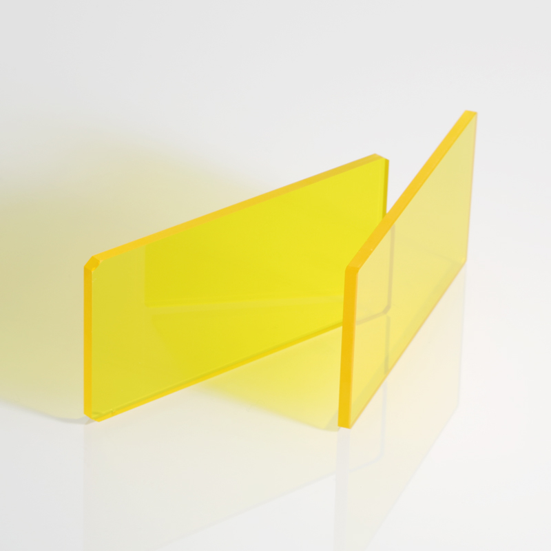
A beauty device filters manufacturer should do more than supply a colored glass plate or quote a filter from one nominal wavelength. The manufacturer should review the light source, required output spectrum, transmission, blocking range, optical density, angle of incidence, substrate, coating durability, dimensions, operating environment, inspection method, prototype quantity, and production demand.
For IPL, laser, LED, imaging, and sensing equipment, the correct filter depends on the complete optical architecture. A suitable manufacturer should therefore be able to evaluate drawings and spectral requirements, explain engineering trade-offs, manufacture samples, provide measurable acceptance criteria, and support repeatable production. Buyers should compare suppliers according to technical capability, documentation, consistency, and communication—not unit price alone.
Definition: What Is a Beauty Device Filters Manufacturer?
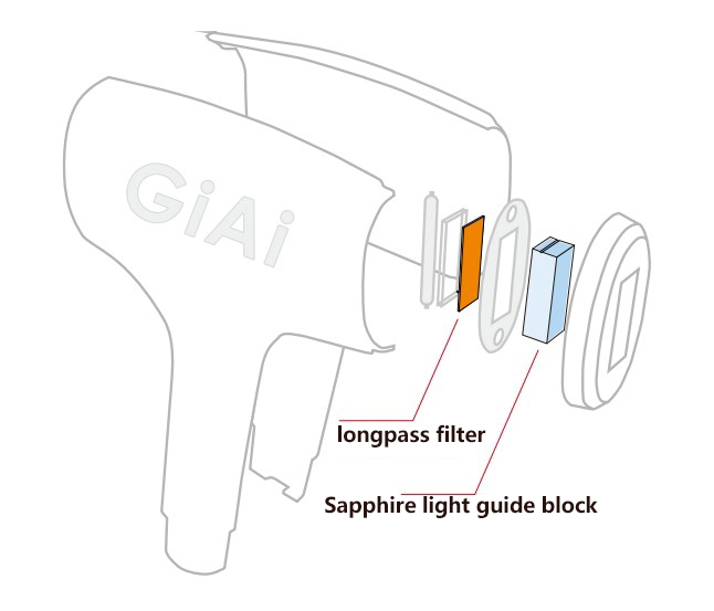
A beauty device filters manufacturer designs or manufactures wavelength-selective optical components for IPL, laser, LED, imaging, sensing, skin-analysis, and related optical equipment.
Depending on the device, these components may transmit a required wavelength range, block unwanted wavelengths, reflect part of the spectrum, reduce optical intensity, separate optical channels, protect an internal assembly, or improve detection contrast.
The manufacturer may supply components such as:
- Longpass filters
- Shortpass filters
- Bandpass filters
- Narrow bandpass filters
- Notch filters
- Neutral density filters
- Dichroic filters
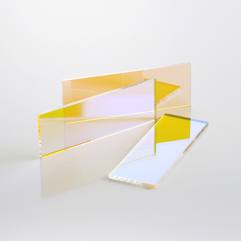
- Coated protective windows
- Polarizing filters
- Custom optical coating services
The filter must be treated as part of the optical system. Its suitability cannot be confirmed from appearance or nominal wavelength alone.
What Does a Beauty Device Filters Manufacturer Need to Understand?
Beauty and medical-aesthetic devices can use very different light sources and optical arrangements.
A broad-spectrum pulsed-light device may use a flashlamp and wavelength-selective filters to define the usable output range. Published optical and clinical literature describes IPL systems as polychromatic pulsed-light systems in which filters help establish the emitted wavelength spectrum.
A laser device is different. Its primary emission may already be concentrated around a defined wavelength. Filters in the system may instead suppress residual emission, isolate a monitoring channel, reject reflected source light, protect a detector, separate imaging and illumination paths, or function as a coated output window.
An LED-based device may require source cleanup, spectral balancing, detector isolation, or wavelength separation. A skin-analysis or fluorescence-related instrument may require narrow wavelength selection, polarization control, stray-light rejection, or separation between illumination and detection bands.
For this reason, a supplier should ask where the component is installed, what light reaches it, and what optical function it must perform.
Which Filter Type Fits the Optical Function?
The application name alone does not determine the filter type. Engineers should first define the optical problem.
| Device or Module | Possible Optical Function | Commonly Evaluated Component | Critical Requirements |
| Broad-spectrum pulsed-light device | Remove unwanted short wavelengths or define an output band | Longpass, shortpass, or bandpass filter | Cut-on wavelength, passband transmission, blocking range, pulse conditions and AOI |
| Laser-based beauty device | Suppress residual emission, separate channels or protect a sensor | Notch, bandpass, dichroic filter or coated window | Laser wavelength, blocking depth, damage risk, polarization and AOI |
| LED beauty device | Clean up source output or separate illumination bands | Bandpass, shortpass or dichroic filter | Source spectrum, transmission, blocking and temperature |
| Skin-analysis imaging system | Improve image contrast and reject illumination leakage | Bandpass, narrow bandpass, polarizing or notch filter | Center wavelength, bandwidth, OD, polarization and detector response |
| Fluorescence-related module | Separate excitation and emission signals | Narrow bandpass and dichroic filters | Spectral separation, blocking range, leakage and AOI |
| Optical monitoring channel | Reduce intensity or isolate a measurement wavelength | Neutral density or narrow bandpass filter | Optical density, spectral neutrality, detector sensitivity and calibration |
| Exposed output assembly | Protect internal optics while maintaining transmission | Coated optical window | Material, flatness, surface quality, strength, coating and cleanability |
| Infrared sensing module | Transmit the sensing band and suppress unwanted visible or infrared light | Infrared bandpass or cutoff filter | Spectral range, substrate absorption, temperature and detector response |
Engineers evaluating broad-spectrum systems may begin with long pass filters, but a longpass component is not automatically sufficient. If the design must reject wavelengths on both sides of the usable range, bandpass filters may be more appropriate.
Detection and imaging channels may require narrow bandpass filters, while monitoring systems may use neutral density filters to reduce intensity without intentionally selecting a narrow color band.
Critical Optical Specifications to Review
Wavelength Range
A specification should define numerical wavelength regions rather than use general phrases such as “visible filter,” “IPL filter,” or “blocks ultraviolet.”
The specification should distinguish among:
- Required transmission band
- Minimum passband transmission
- Transition region
- Blocking wavelength range
- Permitted leakage
- Unspecified wavelengths
- Reflection requirements, when applicable
The source spectrum should be reviewed across all relevant operating modes. The required blocking range should extend far enough to cover source output or detector sensitivity that could affect system performance.
Transmission
Transmission describes how much wanted light passes through the component.
It may be specified as:
- Minimum transmission at selected wavelengths
- Average transmission across a defined band
- Peak transmission
- Transmission uniformity
- Transmission at a specified AOI
- Transmission for a defined polarization state
The highest possible transmission is not always the correct target. Higher transmission, deeper blocking, steeper transitions, broader blocking, angular stability, and coating durability can create competing design requirements.
The manufacturer should identify which requirements are essential and which can be adjusted to improve manufacturability.
Blocking and Optical Density
Out-of-band blocking is as important as in-band transmission.
Optical density is commonly expressed as:
OD = −log₁₀(T)
where T is decimal transmission.
An OD requirement is incomplete unless it is associated with:
- A wavelength range
- An AOI
- A polarization condition, when relevant
- A test resolution
- An instrument measurement limit
- A permitted leakage level
The appropriate blocking depth depends on source intensity, detector sensitivity, system architecture, acceptable leakage, and the device manufacturer’s verification requirements.
Angle of Incidence
Angle of incidence is the angle between the incoming light ray and the surface normal of the filter.
For many interference coatings, changing the AOI changes the measured spectral response. Increasing the angle commonly shifts spectral features toward shorter wavelengths. A converging or diverging beam can also broaden or alter the response because different rays reach the filter at different angles.
A quotation request should therefore state:
- Nominal AOI
- Minimum and maximum AOI
- Beam cone angle
- Collimated, converging, or diverging beam
- Filter orientation
- Polarization state
- Distance from the source
- Illuminated area
Data measured at normal incidence should not automatically be assumed to represent performance inside an angled handpiece or compact optical assembly.
Substrate Material
The substrate supports the coating and affects transmission, absorption, thermal behavior, mechanical strength, thickness, weight, surface quality, and production feasibility.
Material selection should consider:
- Required spectral range
- Internal absorption
- Refractive index
- Thermal expansion
- Thermal conductivity
- Thermal-shock resistance
- Chemical resistance
- Moisture resistance
- Mechanical strength
- Available thickness
- Coating compatibility
- Production quantity and cost
Optical glass may be suitable for many visible and near-infrared filters. Other materials may be required for specialized ultraviolet, infrared, high-temperature, high-power, or mechanically demanding applications.
The material should not be selected only because an existing sample looks similar.
Coating Performance and Durability
An interference coating may contain multiple thin-film layers designed to produce the required transmission and reflection response.
The coating design may need to balance:
- Transmission
- Blocking depth
- Blocking bandwidth
- Transition steepness
- AOI stability
- Polarization sensitivity
- Thermal performance
- Environmental durability
- Manufacturability
- Batch repeatability
- Cost
Current optical-coating frameworks distinguish optical properties, environmental durability, and specific durability testing such as abrasion, adhesion, and resistance to water. The applicable test conditions should be selected according to the component’s actual use rather than added automatically to every drawing.
The buyer should communicate operating temperature, storage temperature, humidity, condensation, cleaning method, chemical exposure, repeated pulse conditions, contamination risk, handling, and expected service conditions.
Mechanical and Surface Requirements
A production drawing should define more than outer length and width.
Relevant requirements may include:
- Diameter or rectangular dimensions
- Thickness and thickness tolerance
- Clear aperture
- Coating aperture
- Edge exclusion
- Chamfer or bevel
- Corner radius
- Flatness
- Parallelism
- Wedge
- Surface quality
- Edge finish
- Coating-side identification
- Orientation mark
- Mounting method
The clear aperture is particularly important. The full mechanical area may not be coated or guaranteed to meet the spectral specification.
For exposed assemblies, optical windows for protective assemblies may require separate evaluation for transmission, flatness, sealing, scratch resistance, cleanability, mechanical strength, and coating durability.
How to Evaluate a Beauty Device Filters Manufacturer
A capable supplier should be assessed through documented engineering and production evidence.
| Evaluation Area | What to Ask the Manufacturer | Why It Matters |
| Application review | Will the supplier review the device function, filter position and source spectrum? | Prevents selection based only on a product name |
| Spectral capability | Can transmission, blocking, OD and transition requirements be evaluated together? | Confirms that the full spectrum is considered |
| AOI evaluation | Can the coating be reviewed at the installed angle and cone angle? | Reduces differences between laboratory data and installed performance |
| Material selection | Can alternative substrates be compared for optical, thermal and mechanical suitability? | Avoids selecting material only by cost or appearance |
| Custom coating | Can the supplier evaluate a new coating design when stock filters do not fit? | Supports proprietary wavelength and mechanical requirements |
| Drawing review | Can dimensions, clear aperture, tolerances and coating orientation be reviewed before quoting? | Reduces mechanical-fit and inspection disputes |
| Sample analysis | Can an existing filter be measured when the original specification is incomplete? | Supports replacement and redesign projects |
| Prototype support | Can development quantities be produced before volume approval? | Enables system-level testing |
| Inspection | Which spectral, dimensional and cosmetic data can be supplied? | Establishes measurable acceptance criteria |
| Production control | How are drawing revisions, batch records and approved samples controlled? | Supports repeat orders and consistency |
| Packaging | How are coated surfaces protected during shipping and handling? | Reduces contamination and coating damage |
| Change communication | How are material, process or measurement changes communicated? | Helps the buyer assess production risk |
GIAI Photonics presents optical filters as a current product category and lists beauty-device longpass configurations within that category. Its existing technical content also addresses drawing review, sample evaluation, prototype testing, inspection, and production considerations.
Practical Manufacturer Selection Checklist
Before selecting a beauty device filters manufacturer, confirm the following.
Optical Information
- Light-source type
- Measured source spectrum
- Required output spectrum
- Passband wavelength range
- Minimum or average transmission
- Cut-on or cutoff definition
- Blocking wavelength range
- Minimum optical density
- Maximum permitted leakage
- Transition-slope requirement
- Spectral ripple tolerance
- Reflection requirements
- AOI and angular range
- Cone angle
- Polarization condition
Power and Operating Conditions
- Peak and average optical power
- Pulse energy
- Pulse duration
- Repetition rate
- Duty cycle
- Illuminated area
- Distance from the source
- Cooling method
- Maximum operating duration
- Housing temperature
- Operating and storage temperature
- Humidity and condensation
- Cleaning process
- Chemical exposure
- Contamination risk
Mechanical Requirements
- Controlled drawing
- Length and width or diameter
- Thickness
- Dimensional tolerances
- Clear aperture
- Coating aperture
- Edge exclusion
- Chamfers or bevels
- Flatness
- Parallelism or wedge
- Surface quality
- Coating-side mark
- Mounting method
Procurement Requirements
- Prototype quantity
- Pilot-production quantity
- Estimated annual demand
- Target production schedule
- Required inspection reports
- Packaging requirements
- Approved drawing revision
- Sample approval procedure
- Golden-sample requirement
- Batch traceability expectations
- Change-notification expectations
Common Mistakes When Selecting a Manufacturer
Comparing Only Unit Price
The lowest quotation may exclude deep blocking, wide blocking ranges, special substrate material, tight tolerances, coating-aperture requirements, inspection reports, custom packaging, or prototype work.
Compare quotations against the same controlled specification.
Requesting Only a Nominal Wavelength
A request for a “550 nm filter” does not explain whether 550 nm is a center wavelength, cut-on wavelength, cutoff wavelength, transmission threshold, or blocking boundary.
Supply a wavelength-versus-transmission requirement instead.
Ignoring Installed AOI
A filter measured at normal incidence may produce a different spectrum when installed at an angle. The supplier needs the real device geometry before finalizing the coating.
Approving a Filter by Color
Visual color cannot verify transmission, blocking depth, spectral leakage, AOI performance, coating durability, or substrate identity.
Approval should be based on measurements and system testing.
Failing to Define the Measurement Method
Two measurements may differ because of instrument resolution, beam geometry, polarization, measurement floor, AOI, or sampling method.
The buyer and manufacturer should agree on how acceptance data will be produced.
Treating Maximum Transmission as the Only Goal
Transmission must be balanced against blocking, transition steepness, durability, thermal performance, angular stability, manufacturability, and repeatability.
Sending a Sample Without Application Information
A sample can provide useful dimensional and spectral data, but the manufacturer should also know the sample’s function, source spectrum, AOI, environment, and required performance changes.
Skipping System-Level Prototype Testing
A spectrometer report does not confirm performance in the complete device. Prototype evaluation should also consider installed spectrum, optical output, temperature, mechanical fit, cleaning, detector response, and assembly consistency.
When to Choose Custom Optical Components
Stock optical filters are appropriate when their verified spectral, mechanical, thermal, and environmental specifications match the complete device.
Choose custom optical filters when:
- A stock filter does not match the source spectrum.
- The device requires a proprietary cut-on wavelength or passband.
- Both short-wave and long-wave blocking are required.
- Out-of-band leakage affects a detector or monitoring channel.
- The filter operates at a non-standard AOI.
- The beam contains a wide angular range.
- Standard dimensions do not fit the housing or handpiece.
- The filter must also function as a protective window.
- Pulse or thermal conditions require application-specific evaluation.
- Cleaning or environmental conditions differ from standard use.
- Batch-specific acceptance data are required.
- An unavailable component must be replaced.
- An existing sample must be characterized.
- Multiple optical functions should be combined into fewer components.
Customization should begin with a specification review, not immediate coating production.
What to Send for Drawing, Sample or Specification Review
A useful quotation package should include:
| Information Category | Recommended Content |
| Application background | Device type, optical function and filter location |
| Source information | Source type, measured spectrum and operating modes |
| Spectral target | Passband, transmission, blocking band, OD and permitted leakage |
| Optical geometry | AOI, cone angle, polarization and beam size |
| Mechanical drawing | Dimensions, tolerances, thickness, clear aperture and coating area |
| Material requirement | Preferred substrate or permission to recommend alternatives |
| Operating environment | Temperature, humidity, cleaning, chemicals and contamination |
| Power conditions | Peak power, average power, pulse energy, pulse duration and cooling |
| Existing sample | Available quantity and required analysis |
| Quality requirements | Spectral, dimensional, surface and coating-appearance criteria |
| Procurement information | Prototype quantity, pilot volume and estimated production demand |
| Development objective | New design, replacement, redesign, performance change or cost review |
For sensing and imaging modules, also provide detector-response information. Small leaks outside the intended passband may be important when the detector remains sensitive in that region.
Systems extending beyond visible wavelengths may require infrared filters for sensing systems, selected according to the source, detector, substrate transmission, thermal conditions, and blocking requirements.
From Prototype to Production
A beauty-device filter should move through a controlled approval process.
1. Specification Review
The manufacturer identifies missing data, conflicting requirements, cost drivers, and manufacturing risks.
2. Feasibility Evaluation
The supplier reviews coating architecture, substrate, dimensions, tolerance, AOI, blocking range, inspection capability, and expected quantity.
3. Prototype Manufacturing
Samples are produced under an identified drawing or specification revision.
4. Supplier-Side Inspection
Depending on the agreement, inspection may include:
- Spectral transmission
- Blocking performance
- Cut-on or center wavelength
- Dimensions
- Thickness
- Clear aperture
- Surface quality
- Coating appearance
- Orientation
- Packaging
5. Device-Level Evaluation
The equipment manufacturer should evaluate:
- Installed output spectrum
- Optical-energy consistency
- Thermal behavior
- Repeated-pulse operation
- Imaging or sensor response
- Stray light
- Mechanical fit
- Cleaning compatibility
- Assembly repeatability
- Performance under intended operating conditions
6. Production Approval
The approved drawing, specification, inspection method, sample status, packaging, and revision should be recorded.
7. Repeat-Order Control
Future orders should reference the approved revision. Any agreed change-notification requirements should be established before volume production.
A properly controlled process reduces the risk of approving a laboratory sample that cannot be reproduced consistently in production.
F. FAQ
1. What does a beauty device filters manufacturer produce?
A beauty device filters manufacturer produces wavelength-selective optical components for IPL, laser, LED, imaging, sensing, skin-analysis, and related devices. Products may include longpass, shortpass, bandpass, narrow bandpass, notch, neutral density, dichroic, polarizing, infrared, and coated-window components.
2. How should I choose a beauty device filters manufacturer?
Evaluate the supplier’s ability to review the complete optical system, understand transmission and blocking requirements, evaluate AOI, recommend substrate materials, manufacture prototypes, inspect spectral and mechanical performance, and maintain controlled production specifications.
3. Which filter is used in an IPL beauty device?
Longpass, shortpass, bandpass, and other filter configurations may be evaluated depending on the source spectrum and required output. Broad-spectrum systems often use cutoff or band-selecting filters, but the correct component must be selected from the complete wavelength, blocking, AOI, power, and device requirements.
4. What information is required for a custom IPL filter quotation?
Provide the source spectrum, required output spectrum, minimum transmission, blocking wavelength range, optical density, AOI, cone angle, dimensions, clear aperture, substrate requirement, pulse conditions, operating temperature, cleaning conditions, prototype quantity, and estimated production demand.
5. Can a manufacturer reproduce an existing beauty-device filter sample?
An existing sample can be measured and evaluated, but exact reproduction may depend on identifying its substrate, spectrum, dimensions, coating behavior, surface requirements, and manufacturing tolerances. The supplier should also understand the component’s function and any required changes.
6. Why does angle of incidence matter?
Changing the angle of incidence can shift the spectral response of an interference filter. A filter tested at normal incidence may therefore perform differently when installed at an angle or placed in a converging or diverging beam.
7. Should I choose a stock or custom beauty-device filter?
Choose a stock filter when its verified spectral, mechanical, thermal, and environmental performance matches the complete device. Choose a custom filter when wavelength ranges, blocking, AOI, dimensions, substrate, coating durability, or production acceptance requirements cannot be met by an existing component.