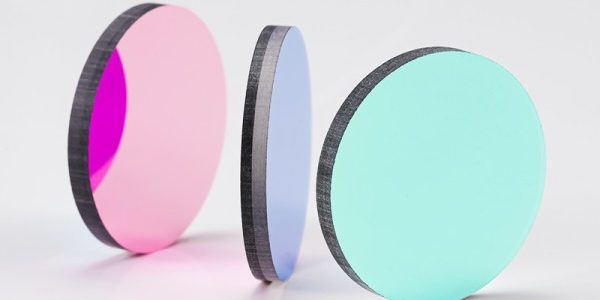
To reduce stray light with optical filters, first identify whether the unwanted radiation differs spectrally or by polarization from the desired signal. A bandpass, longpass, shortpass, notch, neutral density, or polarizing filter can then attenuate the relevant unwanted light before it reaches the detector. The filter must be specified using the actual source spectrum, detector response, blocking wavelength range, optical density, angle of incidence, cone angle, and polarization. Optical filters cannot independently remove in-band scattering, mechanical light leaks, surface contamination, diffraction, or reflections that share the same wavelength as the signal. These problems require system-level measures such as baffles, aperture stops, low-reflectance surfaces, antireflection coatings, improved mounting, cleaning, and optical-path redesign.
What Is Stray Light in an Optical System?
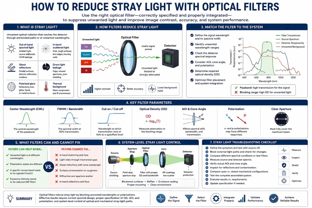
Stray light is optical radiation that reaches a detector or image plane through an unintended path or at an unwanted wavelength. It may produce a raised background level, reduced image contrast, false features, detector saturation, unstable measurements, flare, haze, or ghost images.
Not all stray light has the same origin. It can be divided into several practical categories:
| Stray-light category | Typical source | Can a filter help? |
|---|---|---|
| Out-of-band spectral light | Ambient light, source sidebands, UV or IR leakage | Usually, when the unwanted wavelengths can be defined |
| In-band scattered light | Dust, rough surfaces, lens edges, housing walls | Usually not by spectral filtering alone |
| Ghost reflections | Parallel optical surfaces, detector reflections, windows | Sometimes indirectly, but optical and mechanical changes are usually needed |
| Direct light leakage | Gaps, unused apertures, poor shielding | No; improve enclosure and baffling |
| Polarized glare | Reflections from glass, liquid, polished surfaces, or metals | Sometimes, when the polarization states differ |
| Detector overload | Excessive desired and unwanted optical power | An ND filter may prevent saturation but may not improve signal-to-noise ratio |
| Thermal background | Warm components and environmental radiation in infrared systems | Spectral filtering can help when the target band is separable |
This distinction should be made before selecting an optical filter. A filter is effective only when it attenuates more unwanted radiation than useful signal.
Understand the Signal Before Selecting the Filter
A filter should not be selected from the nominal wavelength of the source alone. The complete measurement chain includes:
- The source spectrum
- The target’s transmission, reflection, absorption, or emission spectrum
- The detector responsivity
- The transmission of lenses, windows, and other optics
- The spectral transmission of the filter
- The optical geometry and angle distribution
- Environmental background radiation
A simplified expression for the detected useful power is:
P_signal ∝ ∫ E_signal(λ) × R_detector(λ) × T_filter(λ) dλ
The detected stray-light power can be represented similarly:
P_stray ∝ ∫ E_stray(λ) × R_detector(λ) × T_filter(λ) dλ
Here, E is the spectral irradiance reaching the filter, R is the detector’s wavelength-dependent responsivity, and T is the filter transmission.
The engineering objective is not merely to maximize peak filter transmission. It is to improve the ratio between the detected useful signal and the unwanted optical background under the actual operating conditions.
For example, a camera may use nominal 850 nm illumination while its silicon detector remains responsive across much of the visible and near-infrared spectrum. A suitable bandpass filter may transmit the useful illumination range while attenuating visible ambient light and unwanted near-infrared wavelengths. The exact bandwidth and blocking range should be based on the source spectrum, detector response, optical angle, and required signal margin.
Choose the Filter Function That Matches the Stray-Light Source
Different optical filters address different spectral problems.
| System problem | Possible filter strategy | Important limitation |
| Broadband ambient light around a narrow illumination wavelength | Bandpass or narrow bandpass filter | The passband must remain wide enough for the source spectrum and angular shift |
| Short-wavelength interference | Longpass filter | It will not block unwanted wavelengths above the cut-on region |
| Long-wavelength or infrared leakage | Shortpass or IR-blocking filter | Detector sensitivity beyond the specified blocking range must be checked |
| A defined laser line or narrow interfering band | Notch filter | The rejected wavelength must remain aligned under the operating AOI |
| Excitation leakage in fluorescence detection | Emission bandpass filter with defined excitation blocking | Filter performance must be reviewed with the complete excitation and emission paths |
| Excessive optical intensity | Neutral density filter | Signal and background may be attenuated together |
| Polarized surface glare | Linear polarizing filter | Benefit depends on polarization orientation and target behavior |
| Multiple separated unwanted bands | Combined or multi-band filter design | Additional transitions can increase design and tolerance complexity |
A filter should therefore be selected by the spectral relationship between the signal and interference, not by a generic request to “block stray light.”
Define the Passband Around the Usable Signal
For a bandpass filter, the passband must transmit the useful signal across all expected variations. Relevant factors include:
- Source center wavelength and spectral width
- Source wavelength drift with temperature or drive conditions
- Target-induced spectral changes
- Manufacturing tolerance
- Angle-of-incidence shift
- Cone angle in converging or diverging beams
- Polarization splitting
- Detector response
- Required signal throughput
A narrower passband can reject more broadband background, but it is not automatically the better choice. If the passband is narrower than the effective source spectrum, useful signal will be lost. A narrow interference filter may also be more sensitive to angular distribution and production tolerance.
For imaging systems with a wide field of view, rays may reach the filter at different angles. Even when the chief ray is close to normal incidence, marginal rays may experience a larger AOI. The result can be a field-dependent spectral shift and nonuniform image response.
The bandwidth should therefore be selected with enough margin for the complete wavelength and angular envelope, not only the nominal source wavelength.
Specify the Entire Blocking Range
A high optical density at one wavelength does not guarantee adequate stray-light suppression across the detector’s full response range.
The blocking specification should state:
- The wavelength interval that must be attenuated
- The minimum optical density across that interval
- Any permitted gaps in blocking
- The operating AOI and polarization
- The spectral measurement conditions
- Whether the requirement applies to an individual filter or assembled system
For a detector sensitive from 400 to 1100 nm, specifying OD4 only near the passband may leave unexamined leakage at shorter or longer wavelengths. Even low transmission at those wavelengths may produce a significant detector response when the background source is strong.
Blocking should therefore be evaluated using the product of background spectrum, filter transmission, and detector responsivity.
Use Optical Density Correctly
Optical density describes attenuation in transmission:
OD = −log₁₀(T)
where T is decimal transmission rather than percentage transmission.
| Optical density | Decimal transmission | Percentage transmission |
| OD2 | 10⁻² | 1% |
| OD3 | 10⁻³ | 0.1% |
| OD4 | 10⁻⁴ | 0.01% |
| OD5 | 10⁻⁵ | 0.001% |
| OD6 | 10⁻⁶ | 0.0001% |
Higher OD provides stronger nominal attenuation, but higher is not always necessary or sufficient.
The required OD depends on:
- The intensity ratio between unwanted and useful light
- Detector dynamic range
- Detector saturation limit
- Permitted background level
- Electronic noise
- Integration time
- Measurement repeatability
- Filter measurement uncertainty
- Leakage around the filter or mount
An OD specification must always include a wavelength range. “OD4 blocking” without a defined range is incomplete.
Very high OD values can also be difficult to verify because the measurement may approach the instrument’s stray-light floor. Test setup, spectral resolution, beam geometry, detector range, and calibration method must be suitable for the specified attenuation.
Account for Angle of Incidence and Cone Angle
Interference filters are angle-sensitive. When the AOI increases, a bandpass or edge feature commonly shifts toward shorter wavelengths. The amount of shift depends on the coating design, effective refractive index, wavelength, polarization, and beam geometry.
A simplified relationship is sometimes written as:
λθ ≈ λ0 × √[1 − (sin²θ / neff²)]
where λ0 is the characteristic wavelength at normal incidence, θ is the external AOI, and neff is an effective refractive-index term.
This expression is useful for illustrating the direction of spectral shift, but it should not replace the actual coating design calculation or measured spectral curves.
In a converging beam, the filter receives a distribution of incident angles rather than one AOI. This can broaden the effective passband, reduce peak transmission, change the edge slope, and create spatial variation across the detector.
The specification should state:
- Nominal AOI
- Maximum AOI
- Full or half cone angle
- Collimated, converging, or diverging beam
- System f-number where relevant
- s- and p-polarization conditions
- Required clear aperture
Performance measured at 0° should not be assumed to remain unchanged at 10°, 20°, or 45°.
Consider Polarization
At nonzero AOI, s- and p-polarized light may experience different spectral responses. The difference can become important for steep-edge filters, narrow bandpass filters, dichroic components, laser systems, and polarized illumination.
A polarizing filter may reduce glare when the unwanted reflection is preferentially polarized and the useful signal has a different polarization state. However, it may also attenuate useful information from birefringent materials, metallic surfaces, stressed transparent parts, or polarization-dependent targets.
Before using polarization to reduce stray light, confirm:
- The polarization state of the source
- The polarization of the unwanted reflection
- Whether the target changes polarization
- The required polarizer orientation
- The effect of camera or object rotation
- AOI-dependent transmission
- Acceptable signal loss
A polarizer should not be treated as a general substitute for spectral filtering or baffling.
Prevent the Filter from Creating New Reflections
Adding a filter introduces at least two additional optical surfaces. These surfaces can create Fresnel reflections, ghost images, flare, or interference effects, particularly when the filter, detector cover glass, and other windows have nearly parallel surfaces.
Possible mitigation measures include:
- Appropriate antireflection coatings on non-filtering surfaces
- Review of filter orientation
- Controlled filter tilt
- Wedged substrates where the optical design permits
- Increased separation from conjugate image planes
- Mechanical masking around the clear aperture
- Low-reflectance interior surfaces
- Avoidance of shiny retaining rings and exposed edges
Tilting an interference filter may move a ghost away from the active image area, but it also changes the filter spectrum. The spectral and ghost-reflection effects must be evaluated together.
An absorptive filter can reduce reflected out-of-band light in some assemblies, while an interference filter may redirect rejected light into another part of the housing. The rejected energy does not disappear; it may be reflected, absorbed, or scattered depending on the filter design and surrounding structure.
Place the Filter Where Its Optical Conditions Are Controlled
There is no single correct filter position for every system.
A filter positioned near the detector can prevent out-of-band radiation from reaching the active sensor. A filter positioned near the source can remove unwanted wavelengths before they travel through the rest of the system. A filter placed in a collimated section may experience a narrower AOI distribution than one placed near a strongly converging beam.
Filter placement should be reviewed for:
- AOI and cone angle
- Beam diameter
- Clear aperture
- Image-plane proximity
- Ghost paths
- Thermal loading
- Contamination exposure
- Ease of cleaning and replacement
- Mechanical tolerances
- Potential light leakage around the mount
The coated area and mechanical holder must cover the complete active beam. A high-performance filter cannot suppress light that bypasses its edge or passes through an uncoated border.
Recognize What Optical Filters Cannot Fix
Optical filters cannot remove all stray light.
If the unwanted light has the same wavelength and polarization as the signal, a spectral filter may attenuate both equally. Common examples include:
- Scattering from dust or contaminated optics
- Reflections from lens barrels and retaining rings
- Light entering through housing gaps
- Out-of-field light bypassing the intended optical path
- Surface scatter from rough or damaged optics
- Diffraction from apertures
- In-band ghost reflections
- Detector cover-glass reflections
- Internal reflection inside windows or substrates
These problems may require:
- Baffles and field stops
- Aperture stops
- Source shielding
- Blackened mechanical surfaces
- Edge blackening
- Antireflection coatings
- Improved optical surface quality
- Better enclosure sealing
- Correct lens and window mounting
- Contamination control
- Changes to optical spacing or tilt
- Stray-light simulation and path analysis
A complete stray-light strategy usually combines spectral filtering with optomechanical control.
Why Neutral Density Filters Do Not Always Improve Signal-to-Noise Ratio
A neutral density filter reduces optical intensity over a defined wavelength range. It can help prevent detector saturation, extend measurement range, balance channels, or support calibration.
However, when the ND filter attenuates the useful signal and the unwanted background by the same factor, the optical signal-to-background ratio remains approximately unchanged. Detector noise and exposure adjustments may cause the final signal-to-noise ratio to improve, remain unchanged, or become worse.
An ND filter is therefore most useful when the problem is excessive power rather than spectral contamination. For broadband stray-light suppression, a wavelength-selective filter is generally more effective when the useful signal occupies a limited spectral range.
A Practical Stray-Light Troubleshooting Procedure
1. Define the observed symptom
Record whether the problem appears as:
- Uniform background elevation
- Local flare
- Ghost image
- Reduced contrast
- Color or spectral bias
- Detector saturation
- Field-dependent brightness
- Temperature-dependent drift
- Random instability
Different symptoms suggest different optical paths.
2. Test with the intended source disabled
Measure the detector output with the controlled source off while keeping the detector settings unchanged. This helps estimate ambient, thermal, electronic, and housing-related background.
3. Block external light paths
Cover individual apertures, seams, indicator lights, viewing windows, and cable openings. A large response change indicates mechanical leakage rather than inadequate filter OD.
4. Compare different spectral conditions
Use known illumination bands or temporary test filters to identify which wavelengths contribute to the background. Test filters should be used only for diagnosis unless their full spectral and environmental performance is known.
5. Measure the source and detector spectra
Compare the useful source spectrum with the detector response. Check for LED sidebands, residual laser emission, phosphor emission, infrared leakage, UV leakage, or broad detector sensitivity outside the target band.
6. Verify the actual filter angle
Measure or estimate the chief-ray AOI and angular cone. A filter that works in a collimated bench test may shift when installed in a fast or wide-angle imaging system.
7. Inspect for reflections and contamination
Examine filters, windows, lenses, detector covers, mounts, and housing surfaces. Dust, fingerprints, coating damage, exposed polished edges, and shiny retaining components can generate in-band scatter that stronger blocking will not remove.
8. Compare open and closed mechanical configurations
Changes caused by covers, mounts, retaining rings, or internal shields often reveal a structural stray-light path.
9. Test the complete assembled system
Confirm background level, signal throughput, image uniformity, ghost behavior, and spectral response under the intended temperature, field angle, polarization, source power, and detector settings.
10. Convert the result into a measurable specification
The final requirement should define wavelength, passband, transmission, blocking range, OD, AOI, cone angle, polarization, dimensions, clear aperture, substrate, environmental conditions, and inspection method.
Illustrative Filter Specification
The following is a hypothetical specification intended only to show the required structure:
| Parameter | Illustrative requirement |
| Target signal | 850 nm LED illumination |
| Passband | Defined around the measured LED spectrum |
| Minimum transmission | Specified across the usable passband |
| Blocking range | 400–780 nm and 920–1100 nm |
| Blocking level | Defined separately for each wavelength region |
| Nominal AOI | 0° |
| Maximum ray angle | Based on the actual imaging cone |
| Polarization | Unpolarized or separately specified |
| Clear aperture | Larger than the maximum active beam |
| Test conditions | Defined spectral resolution and beam geometry |
The final values must be established from the actual source, detector, optical path, environment, and measurement target. They are not universal recommendations.
Conclusion
Optical filters reduce stray light most effectively when the unwanted radiation can be separated from the useful signal by wavelength or polarization. Successful selection requires more than choosing a center wavelength or requesting a high OD value. Engineers must define the source spectrum, detector response, passband, blocking range, AOI, cone angle, polarization, filter placement, and measurement conditions.
When the stray light shares the same wavelength as the useful signal, stronger spectral blocking may provide little benefit. Baffles, aperture control, antireflection coatings, low-reflectance mechanical surfaces, contamination control, and optical-path changes must then be considered as part of the complete system.
Engineers may provide wavelength requirements, source and detector spectra, drawings, samples, AOI, tolerances, operating conditions, and inspection requirements to GIAI Photonics for further component evaluation.
FAQ
Can optical filters completely eliminate stray light?
No. Optical filters can attenuate unwanted wavelengths or polarization states, but they cannot completely eliminate every stray-light path. In-band scattering, housing leaks, diffraction, contamination, ghost reflections, and light bypassing the clear aperture may remain. Effective suppression normally requires a combination of spectral filtering, baffles, field stops, aperture control, antireflection coatings, surface treatment, cleaning, and mechanical shielding.
Is a higher optical density always better for stray-light suppression?
No. Higher OD provides stronger attenuation only within the wavelength range and test conditions for which it is specified. Excessive blocking outside the necessary range may increase complexity without improving system performance. The required OD should be calculated from source intensity, background spectrum, detector response, dynamic range, exposure time, electronic noise, and acceptable residual background.
Does a narrower bandpass always reduce more stray light?
A narrower passband generally rejects more broadband background, but it can also reduce useful signal. It may become more sensitive to source wavelength drift, AOI, cone angle, temperature, polarization, and manufacturing tolerance. The passband must remain wide enough to transmit the useful spectrum under all operating conditions.
Can a neutral density filter improve signal-to-noise ratio?
Not necessarily. An ND filter normally attenuates both the desired signal and background within its attenuation range. It is useful for preventing saturation, balancing optical channels, extending measurement range, or controlling optical power. It improves signal-to-background ratio only when it attenuates the unwanted component differently from the useful signal or changes the detector’s operating condition beneficially.
Why does stray light remain after installing a high-OD filter?
Possible causes include an incomplete blocking range, AOI-induced spectral shift, leakage outside the measured wavelength interval, light bypassing the filter edge, in-band scattering, mechanical gaps, contaminated surfaces, ghost reflections, detector cover-glass reflections, or measurement limitations. The complete optical and mechanical path should be tested before specifying a stronger filter.