Custom C-Lens for Fiber Collimation and Optical Communication
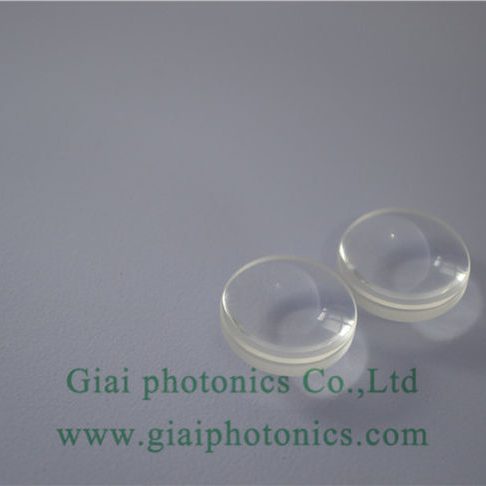
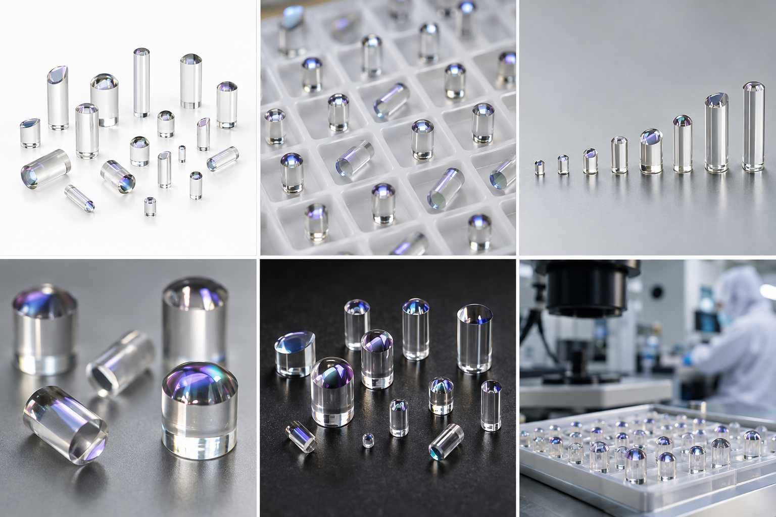
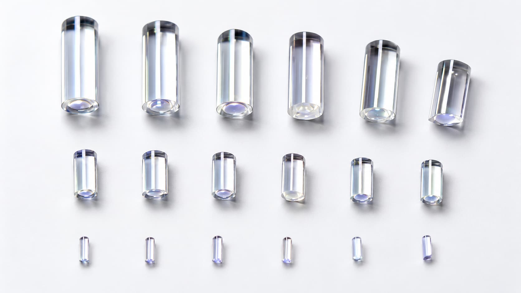
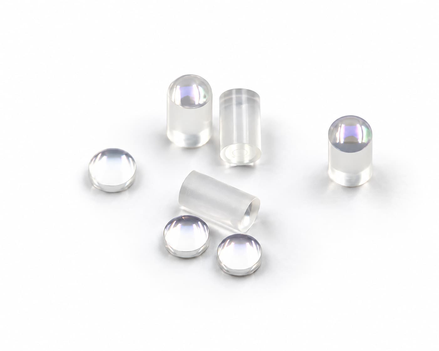
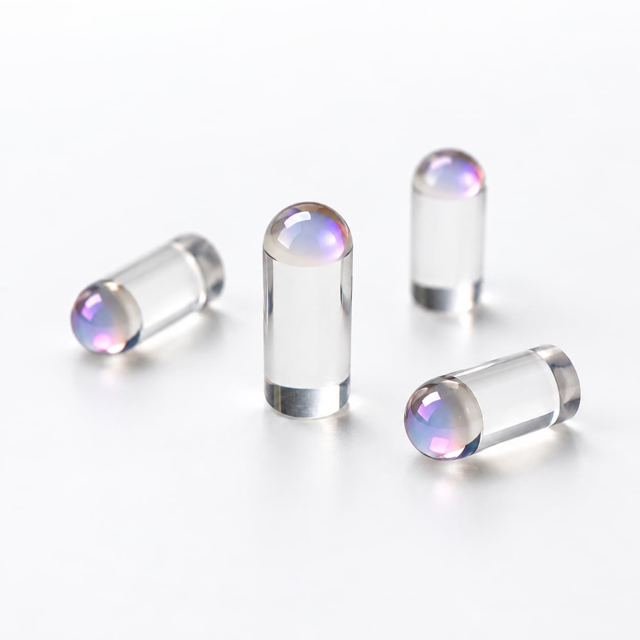
A C-Lens is a compact cylindrical micro-optic used for fiber collimation, optical coupling and fiber-to-free-space beam interfaces. Its spherical optical surface provides the refractive power required to control the beam, while the opposite end can be configured as a flat or angled surface according to the optical layout.
GIAI reviews C-Lens projects against the drawing, optical requirements, geometry, coating conditions and inspection criteria before defining the manufacturing route.
Compact Micro-Optics for Fiber-to-Free-Space Interfaces
Light emerging from an optical fiber is divergent. A C-Lens can be positioned relative to the fiber to reduce that divergence and form a collimated or near-collimated free-space beam. The same optical principle can be used in reverse to couple an appropriate free-space beam toward a fiber.
Beam behavior depends on the complete optical configuration, including lens geometry, refractive index, operating wavelength, fiber characteristics and the spacing between the fiber and lens. These parameters should therefore be defined as part of the optical system rather than treated independently.
Compact Cylindrical Geometry
Suitable for fiber-optic assemblies and compact photonic systems where available package space is limited.
Precision Spherical Surface
The spherical optical surface provides the primary refractive power used for beam control.
Flat or Angled End Face
End-face geometry can be defined according to the optical path, mechanical interface and reflection requirements.
Application-Specific AR Coating
AR coating requirements can be reviewed according to operating wavelength, substrate and application conditions.
C-Lens Precision Optical Components
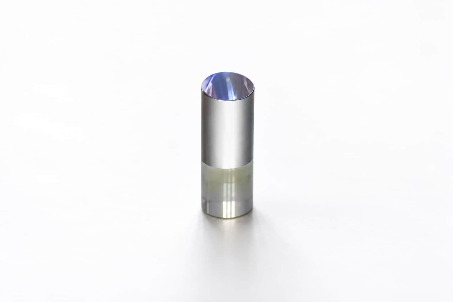
C-Lens Specifications
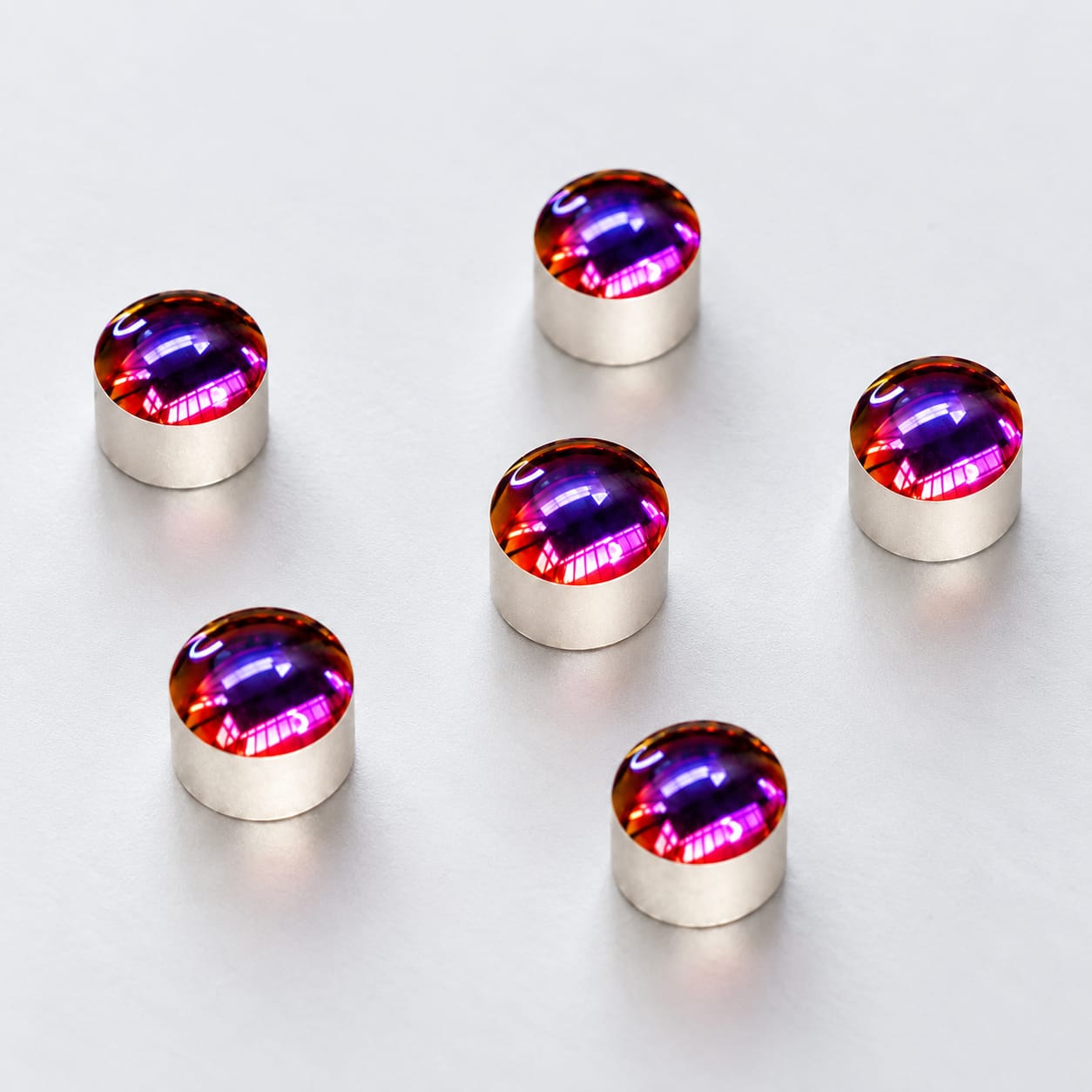
C-Lens components are available in compact geometries for fiber collimation, optical coupling and optical communication applications. Dimensions, wedge angle, surface requirements and AR coating can be selected according to the optical configuration and application requirements.
| Parameter | Specification | Unit |
|---|---|---|
| Typical Diameter | 1.0 or 1.8, +0.005 / -0.01 | mm |
| Length Tolerance | < ±0.04 | mm |
| Typical Wedge Angle | 0°, 6°, 8°, 9°, 12° | ° |
| Angle Tolerance | ±0.5 | ° |
| Surface Figure | < λ/4 | — |
| Max. Power Handling | < 600 | mW |
| Surface Quality | Better than 20/10, N ≤ 2 | Scratch / Dig |
| AR Coating |
R < 0.25% @ λ ± 40 nm or 1250–1650 nm |
— |
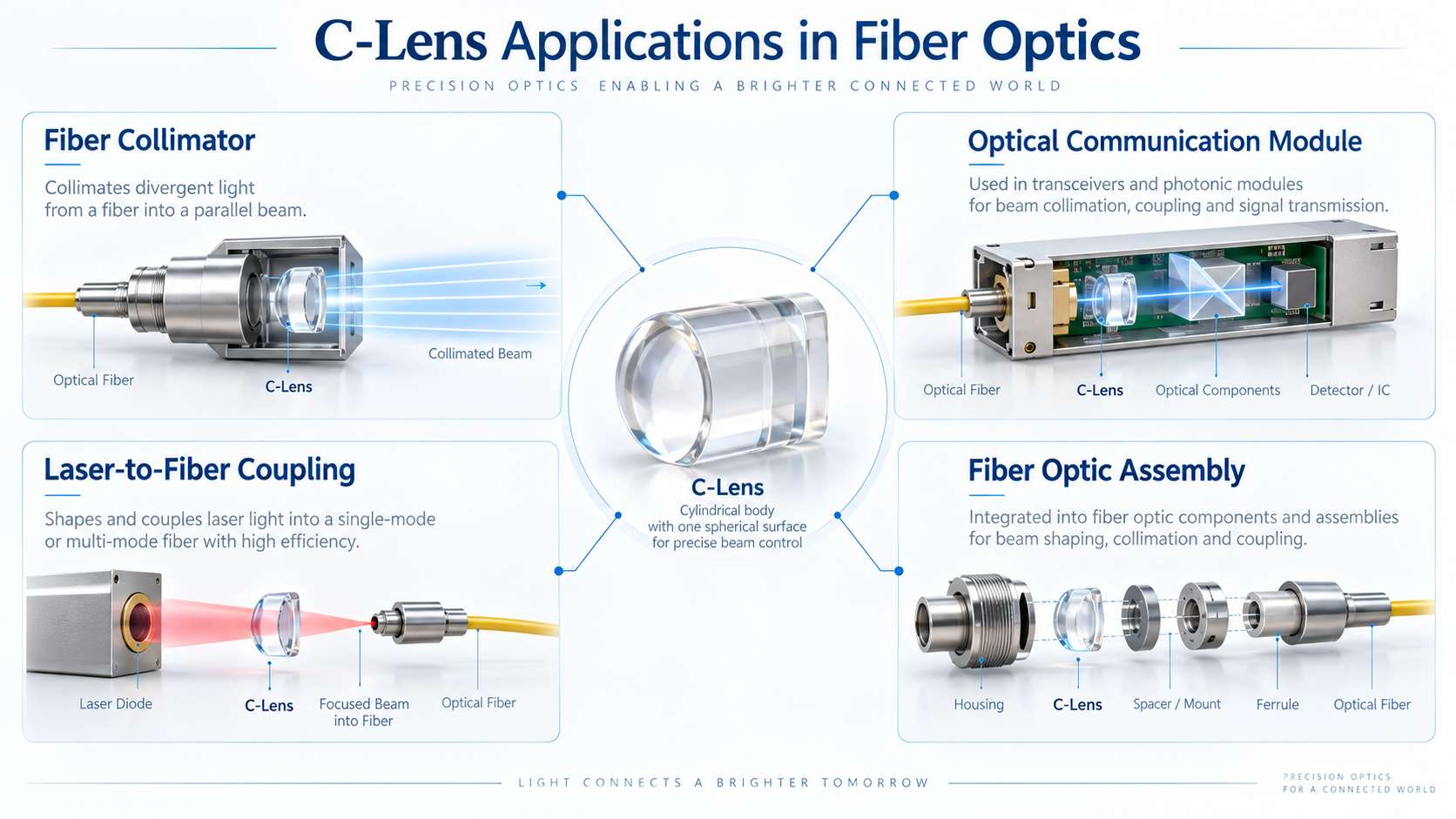
Key C-Lens Geometry Parameters
Diameter, overall length, spherical radius and end-face angle are among the main geometric parameters used to define a custom C-Lens.
These dimensions affect both the mechanical interface and the optical configuration. The appropriate values should therefore be reviewed together with the fiber characteristics, working distance and required beam behavior.
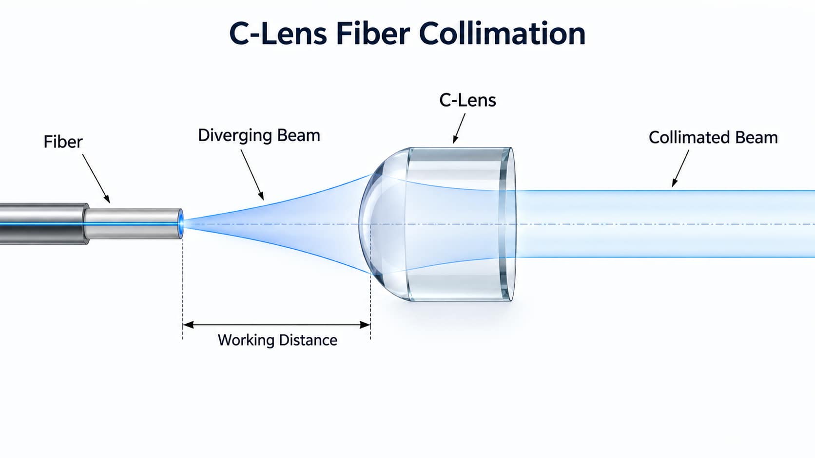
How a C-Lens Collimates Fiber Output
Light leaving a fiber expands as it propagates. When the fiber and C-Lens are positioned according to the optical design, the spherical surface changes the beam propagation and reduces the output divergence.
The resulting beam diameter, divergence and working distance depend on the lens geometry, wavelength, fiber characteristics and fiber-to-lens spacing.
C-Lens Applications in Fiber Optics
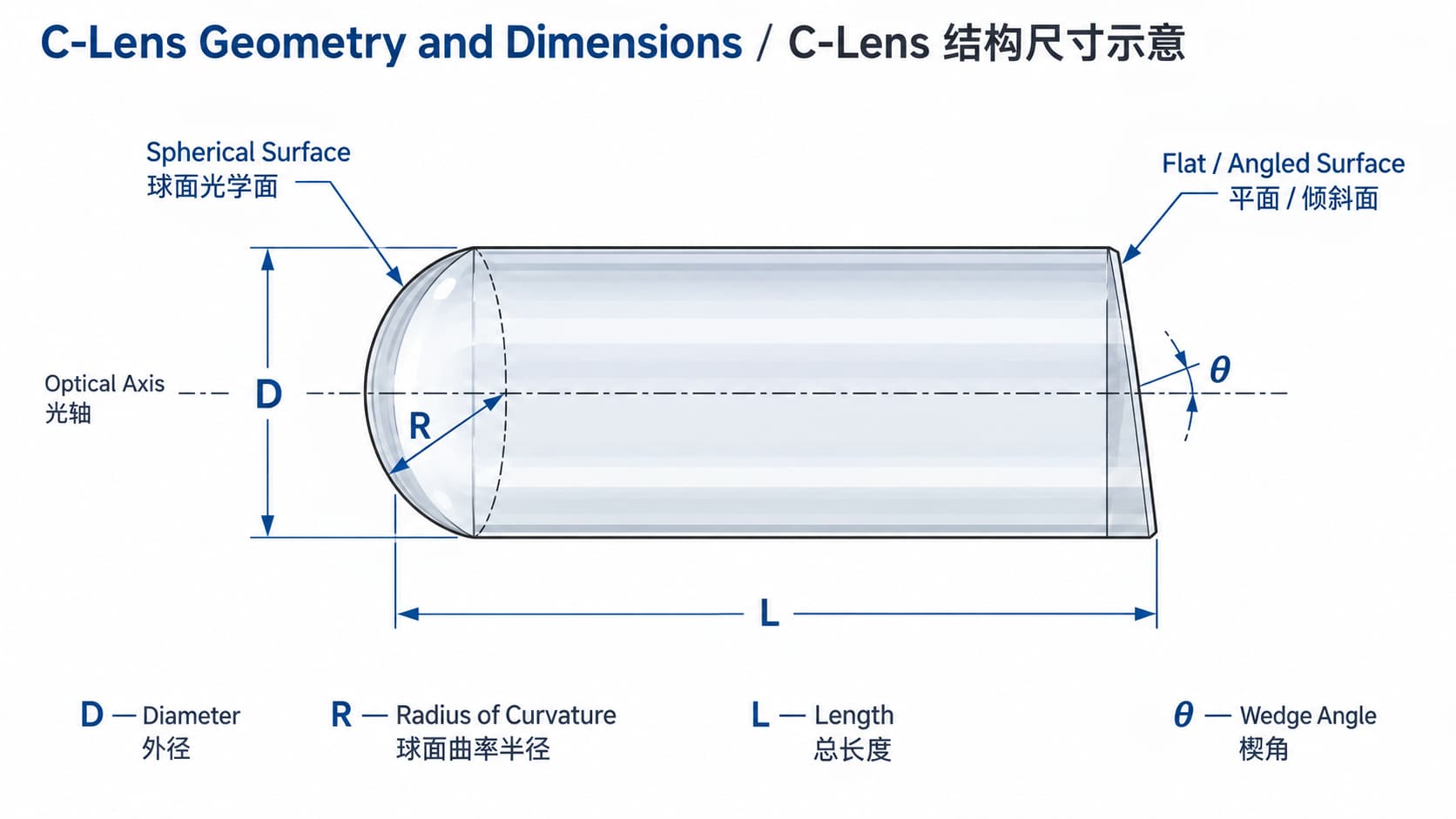
Typical Applications
Fiber Collimators
Used to transform divergent fiber output into a collimated or near-collimated free-space beam.
Optical Communication Modules
Used in compact optical paths that transfer light between fibers and free-space optical components.
Laser-to-Fiber Coupling
Suitable for optical interfaces where laser light must be coupled toward a fiber or fiber output must be delivered into a free-space optical path.
Fiber Optic Assemblies
Can be integrated into compact fiber-optic and photonic assemblies requiring beam control and coupling.
C-Lens Customization
Precision Fabrication, Coating and Inspection
GIAI reviews custom optical projects against the drawing, sample, optical requirements, material, geometry, coating conditions and inspection criteria before defining the manufacturing route.
Depending on the component requirements, the manufacturing route may involve grinding, precision grinding, optical polishing, cleaning, geometry processing, optical coating and inspection. The actual process sequence is determined by the individual C-Lens specification.
Request a Custom C-Lens
Send your drawing, optical specification or existing sample together with the operating wavelength, fiber parameters, dimensions, radius, working distance, coating requirements, inspection criteria and expected quantity for technical review.
Start a Custom Project