
Technical Resources
905 nm vs 1550 nm LiDAR Optical Filters
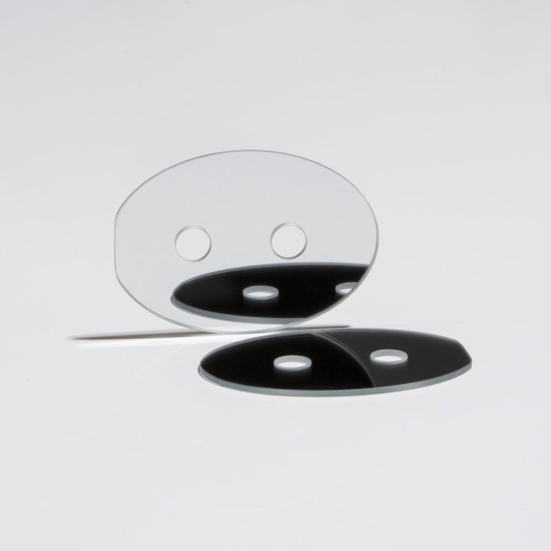
Choosing between 905 nm vs 1550 nm LiDAR optical filters is not simply a matter of moving the center wavelength of the same bandpass filter. The two wavelengths are associated with different laser sources, detector materials, eye-safety constraints, ambient-light conditions and receiver architectures. Those differences directly affect how the optical filter should be specified.
A 905 nm receiver commonly uses a silicon detector, while a 1550 nm receiver typically uses a detector sensitive in the short-wave infrared. The filter in front of that detector must transmit the useful return while rejecting as much unwanted optical background as practical. As a result, center wavelength, FWHM, blocking range, optical density, angle of incidence and substrate selection all have to be considered together.
905 nm vs 1550 nm LiDAR Optical Filters at a Glance
| Engineering Factor | 905 nm LiDAR | 1550 nm LiDAR |
|---|---|---|
| Wavelength region | Near infrared | Short-wave infrared |
| Typical detector family | Silicon PIN, APD, SPAD or SiPM architectures | InGaAs-based PIN, APD or SPAD architectures are common |
| Eye-safety implication | 905 nm radiation can reach the retina, so allowable exposure constrains transmitter design | 1550 nm is strongly attenuated before reaching the retina, allowing a higher exposure limit under many operating conditions |
| Solar background | Generally higher terrestrial spectral irradiance around the operating band | Generally lower terrestrial solar background around the operating band, but not zero |
| Filter blocking range | Usually defined around the actual spectral sensitivity of the silicon receiver | Usually defined around the actual SWIR detector response |
| Passband width | Derived from source spectrum, temperature drift, tolerance and AOI | Derived from the same system variables; there is no universal 1550 nm FWHM |
| AOI sensitivity | Interference passband shifts with angle | Interference passband also shifts with angle |
| System cost tendency | Often benefits from the mature silicon detector ecosystem | SWIR detectors and associated components may increase system cost |
What the LiDAR Receiver Filter Actually Does
A LiDAR receiver is intended to detect a weak optical return from the transmitted laser. The receiving aperture, however, also collects sunlight, artificial illumination, reflections from optical surfaces and other stray radiation.
A narrow bandpass filter placed in the receiving optical path transmits a spectral region containing the laser return while attenuating selected wavelengths outside that region. It therefore reduces the amount of unwanted optical power reaching the photodetector.
The filter does not create the ranging signal, determine the laser power or independently establish detection range. Its function is spectral discrimination within a larger signal-to-noise budget.
This distinction matters when comparing 905 nm and 1550 nm systems. The useful signal may move from one wavelength to another, but the detector response and background spectrum change with it. The filter specification has to follow the complete receiver architecture.
Detector Technology Is One of the Largest Differences
905 nm and silicon detectors
Silicon remains responsive around 905 nm, which makes silicon PIN photodiodes, avalanche photodiodes, SPADs and related detector architectures practical for this wavelength.
For the filter designer, this means that out-of-band blocking should be evaluated across the wavelengths where the actual silicon detector can produce a meaningful electrical response. Blocking only a narrow region immediately beside 905 nm may leave significant ambient radiation elsewhere in the detector sensitivity range.
1550 nm and SWIR detectors
Silicon becomes effectively insensitive before reaching 1550 nm, so 1550 nm LiDAR normally requires a detector designed for the short-wave infrared. Standard InGaAs detector technology, for example, commonly covers a substantial portion of the approximately 0.9–1.7 µm region.
That changes the blocking problem. A 1550 nm filter should be specified according to the response curve of the selected SWIR detector rather than copying the blocking range used for a 905 nm silicon receiver.
Eye Safety Is a System Property, Not a Filter Property
The eye transmits significant 905 nm radiation toward the retina. At wavelengths beyond approximately 1400 nm, absorption in the anterior portions of the eye becomes much stronger, so considerably less energy reaches the retina.
This is why 1550 nm systems can often operate with a higher permissible optical exposure than 905 nm systems under comparable laser-safety calculations. The additional transmitter-energy budget can be useful when designing long-range LiDAR.
It is nevertheless incorrect to state that every 1550 nm LiDAR is automatically eye-safe, or that every 905 nm LiDAR is unsafe. Laser classification depends on parameters including emitted power or pulse energy, pulse duration, pulse repetition pattern, divergence, aperture, scan behavior and exposure conditions.
The optical bandpass filter on the receiving side does not determine the laser safety classification.
Solar Background Changes the Filtering Problem
Outdoor LiDAR operates against broadband solar illumination. Although the receiver is looking for a narrow laser wavelength, sunlight entering the same aperture can generate background photocurrent and photon noise.
Terrestrial solar spectral irradiance is generally lower around 1550 nm than around 905 nm because the solar spectrum reaching ground level contains wavelength-dependent atmospheric absorption features. This can give a 1550 nm receiver a useful background-light advantage.
It does not remove the need for optical filtering. Solar irradiance at 1550 nm is not zero, and the detector may respond over a much broader spectral interval than the transmitted laser.
The practical background reaching the detector depends on several variables:
- receiver aperture;
- field of view;
- detector spectral responsivity;
- filter bandwidth;
- out-of-band blocking;
- target reflectance;
- sun position and illumination;
- internal stray light.
A narrower filter can reduce broadband background, but only if the useful return remains inside the passband under all operating conditions.
Do Not Make the FWHM Narrower Than the Optical System Can Support
Full width at half maximum, or FWHM, describes the wavelength interval between the two points where transmission falls to half of the peak transmission.
FWHM is not the same as center wavelength. A filter can have the correct center wavelength and still have an inappropriate bandwidth.
It is tempting to specify the narrowest possible filter because a narrower spectral window admits less broadband background. In a real LiDAR receiver, however, the filter must accommodate more than the nominal laser wavelength.
The spectral budget may include:
- laser linewidth;
- source wavelength tolerance;
- wavelength variation with temperature and drive conditions;
- filter manufacturing tolerance;
- filter temperature shift;
- angle-of-incidence shift;
- the angular distribution of rays inside the receiver.
If these effects move part of the return outside the filter passband, reducing FWHM further can decrease useful signal instead of improving system performance.
The correct FWHM is therefore obtained from a tolerance budget, not from the nominal wavelength alone.
Angle of Incidence Matters at Both 905 nm and 1550 nm
Most high-performance LiDAR bandpass filters are multilayer interference filters. Their spectral response depends on the angle at which light enters the coating.
As angle of incidence increases, a conventional interference-filter passband generally shifts toward shorter wavelengths. The phenomenon is commonly described as a blue shift.
A simplified first-order relationship can be written as:
λθ = λ0 × √[1 − sin²(θ) / neff²]
where λ0 is the reference wavelength, θ is the external incidence angle and neff represents an effective refractive index of the multilayer coating. The equation is useful for understanding the direction of the shift, but actual performance must come from the specific coating design or measurement.
This becomes especially important when the filter is installed inside a fast receiver lens. The filter may receive a cone of rays rather than one collimated ray at 0°. Different rays can therefore experience different effective passbands.
A spectrum measured only at normal incidence should not automatically be used to predict performance in a receiver operating across a substantial angular range.
Polarization at oblique incidence
At larger incidence angles, S- and P-polarized light may also experience different spectral responses. If the LiDAR architecture creates a defined polarization state or substantial oblique incidence, polarization should be included in both coating design and spectral verification.
Optical Density Must Be Defined Together With the Blocking Range
Optical density describes attenuation and is related to fractional transmission by:
OD = −log10(T)
For example, OD4 corresponds to a fractional transmission of 10−4, or 0.01%.
This number alone does not specify a useful LiDAR filter. An engineer also needs to state where that blocking must occur.
A 905 nm system and a 1550 nm system may require very different rejection intervals because their photodetectors respond to different spectral regions. The blocking specification should therefore be based on the detector response, ambient spectrum, other optical emitters in the system and the allowable background power.
There is no engineering basis for assuming that every 905 nm or every 1550 nm LiDAR requires the same OD value.
Peak Transmission Is Not the Same as Useful Passband Transmission
Peak transmission reports the highest transmission value reached somewhere inside the passband. It does not describe how much of the entire laser-return spectrum reaches the detector.
For LiDAR, minimum transmission across a defined useful wavelength interval or average transmission over that interval may be more meaningful than a single peak value.
This becomes particularly important when wavelength tolerance, temperature and AOI are included. A filter may show a high peak transmission at room temperature and normal incidence while producing significantly different transmission at the edge of the system’s operating envelope.
Does 1550 nm Perform Better in Fog and Rain?
Weather performance should not be reduced to a simple statement that one wavelength “penetrates fog” better than the other.
Fog attenuation is dominated by interactions between light and suspended water droplets. Experimental and modeled comparisons have found that the extinction coefficients of 905 nm and 1550 nm in representative fog conditions can be relatively close when compared at the same emitted optical power.
At the same time, water absorption is wavelength dependent, and 1550 nm does not automatically have lower atmospheric loss under every condition.
Real LiDAR performance in fog, rain or spray is also affected by transmitter power, receiver aperture, detector sensitivity, filtering, pulse processing, target reflectance and backscatter from particles.
Therefore, weather performance should be validated at the complete system level rather than inferred from filter wavelength alone.
Substrate and Coating Performance Must Be Verified at the Actual Wavelength
The transmission range of an uncoated optical substrate is not the same as the transmission of the finished filter.
A complete LiDAR filter includes the substrate, multilayer coating and usually additional surface or mechanical requirements. The final optical behavior depends on material absorption, coating design, thickness, angle of incidence and environmental conditions.
For a 1550 nm filter in particular, the chosen substrate and every coating layer must be appropriate for operation in the SWIR region. A material name alone is not sufficient evidence of finished-component transmission.
Similarly, a coating that performs well at 905 nm cannot simply be assumed to provide equivalent performance at 1550 nm. The multilayer stack must be designed for the intended spectral region.
How to Specify a 905 nm or 1550 nm LiDAR Filter
A practical filter specification should start from the complete receiver rather than from a catalog wavelength.
- Define the laser spectrum. Include nominal wavelength, linewidth, tolerance and expected wavelength change with temperature and operating conditions.
- Define the detector. Use its actual spectral response to determine where unwanted light can generate signal or noise.
- Define the optical geometry. State nominal AOI, angular range, receiver F-number or cone angle, field position and filter location.
- Set the useful passband. Choose CWL and FWHM only after accounting for laser and optical tolerances.
- Define transmission correctly. State whether the requirement refers to peak, minimum or average transmission.
- Define blocking by wavelength region. Specify both OD and the spectral interval over which it applies.
- State polarization conditions. This becomes increasingly important at oblique incidence.
- Add mechanical requirements. Define dimensions, thickness, clear aperture and mounting constraints separately from spectral properties.
- Add optical-quality requirements where necessary. Surface quality, flatness and transmitted wavefront should reflect the actual location and function of the filter.
- Verify the installed receiver. A standalone spectral measurement does not establish complete LiDAR performance.
905 nm or 1550 nm: Which Filter Should You Choose?
The wavelength should normally be selected at the LiDAR system level before the receiver filter is specified.
905 nm is often appropriate when the architecture is built around silicon detection, mature semiconductor components, compact packaging and cost-sensitive integration. The receiver filter then has to manage the source tolerance, silicon detector response and potentially substantial outdoor optical background around that architecture.
1550 nm is often appropriate when the system can justify a SWIR detector and wants to take advantage of the higher allowable exposure associated with wavelengths beyond the retinal-hazard region. Lower solar background around the operating wavelength may provide another useful contribution to the receiver noise budget.
The filter is a consequence of that system decision. A properly designed 905 nm filter is not an inferior version of a 1550 nm filter, and a 1550 nm filter is not automatically a higher-performance component.
For either wavelength, the engineering objective is the same: transmit the complete useful return under real operating conditions while suppressing unwanted optical energy over the wavelengths to which the receiver is sensitive.
Conclusion
The most important difference in 905 nm vs 1550 nm LiDAR optical filters is not the 645 nm separation between their nominal center wavelengths. It is the different optical ecosystem surrounding each filter.
905 nm commonly pairs with silicon detectors and a mature near-infrared component platform. 1550 nm normally moves the receiver into the SWIR detector regime and can provide a larger eye-safety power budget together with lower solar background around the operating wavelength.
For both systems, CWL, FWHM, transmission, blocking OD, blocking range, AOI, polarization and substrate performance should be derived from the actual optical path. The narrowest passband or highest OD number is not automatically the best specification.
The most reliable approach is to treat the laser source, receiver optics, filter and detector as one spectral system and qualify the finished assembly under its real angular, thermal and environmental conditions.
Frequently Asked Questions
Is a 1550 nm LiDAR optical filter always better than a 905 nm filter?
No. A 1550 nm filter is not inherently better than a 905 nm filter. The correct wavelength depends on the laser source, detector, eye-safety design, required range, receiver architecture, cost and operating environment. A 905 nm system can use mature silicon detector technology, while 1550 nm normally requires a SWIR-sensitive detector. Filter performance should therefore be judged against the requirements of the complete LiDAR receiver rather than by wavelength alone.
How narrow should a LiDAR bandpass filter be?
The passband should be only as narrow as the complete optical tolerance budget allows. The filter must transmit the laser return after accounting for source linewidth, wavelength tolerance, temperature drift, coating tolerance, angle-of-incidence shift and the angular cone inside the receiver. Reducing FWHM can suppress additional broadband background, but an excessively narrow filter can also attenuate the useful return. There is therefore no universal FWHM that applies to every 905 nm or 1550 nm LiDAR.
Does a 1550 nm LiDAR filter require higher optical density than a 905 nm filter?
Not necessarily. Required optical density depends on the detector response, background spectrum, receiver field of view, other optical sources and allowable noise rather than the nominal LiDAR wavelength alone. OD must also be specified together with a wavelength range. A filter described only as “OD4” or “OD6” is incomplete because it does not state where that attenuation applies. The blocking requirement should be calculated from the actual receiver and detector.
Can a 905 nm or 1550 nm bandpass filter be used at an oblique angle?
Yes, but the filter must be designed or verified for the actual angle of incidence. Multilayer interference filters normally shift toward shorter wavelengths as AOI increases, and larger angles can also create different responses for S and P polarization. In a converging LiDAR receiver, different rays can reach the filter at different angles simultaneously. A spectrum measured at 0° therefore should not automatically be assumed to represent performance in the assembled optical system.
Does using 1550 nm automatically make a LiDAR system eye-safe?
No. The longer wavelength generally permits higher optical exposure because 1550 nm radiation is strongly absorbed before reaching the retina, but laser safety remains a system-level requirement. Classification depends on factors such as optical power or pulse energy, pulse duration, repetition rate, beam divergence, scanning pattern, aperture and exposure geometry. A receiving bandpass filter does not determine the laser-safety classification of the transmitter.
