
Technical Resources
Ambient Light Rejection Filter for ToF Sensors: A Guide
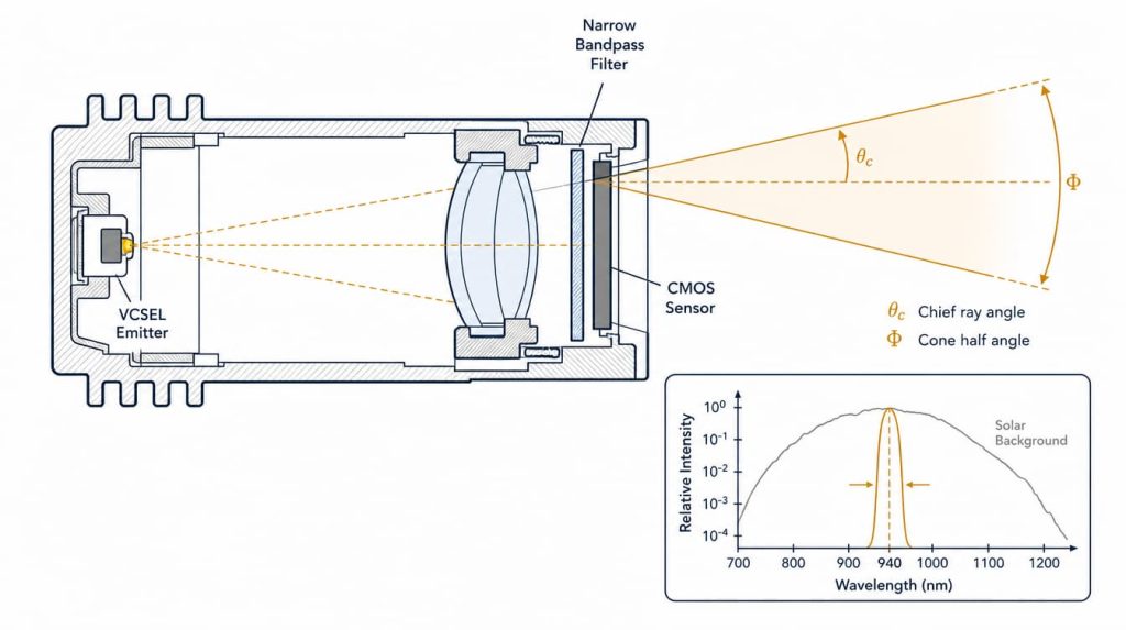
An ambient light rejection filter for a time-of-flight sensor is a narrow bandpass interference filter placed in the receive path that transmits the illuminator wavelength, normally 850 nm or 940 nm, and blocks everything else across the detector’s spectral response. It matters because time-of-flight (ToF) depth precision is limited by the shot noise of background photons, so removing out-of-band light converts directly into range and repeatability. The difficult part is not deciding to use a filter. It is choosing a passband narrow enough to reject sunlight and wide enough to still contain the laser line after emitter binning, thermal drift, and angle-of-incidence shift.
This article covers the noise physics that sets the requirement, the parameters you read off a filter datasheet, a worked passband error budget, and the specification mistakes that cost real range in the field.
Why ambient light limits time-of-flight range
For indirect time-of-flight (iToF) sensors using the standard four-tap demodulation model, depth standard deviation follows
σ_z = (c / 2f_mod) × (1 / √8) × √(A + B) / (c_d × A)
where c is the speed of light, f_mod the modulation frequency, A the demodulation amplitude in electrons, B the offset (background plus the DC part of the active signal), and c_d the demodulation contrast. When ambient light dominates, B >> A, and the expression collapses to a simple proportionality:
σ_z ∝ √B / A
Noise grows with the square root of background, not linearly. That is the single fact that governs filter specification.
For direct time-of-flight (dToF) sensors built on single-photon avalanche diodes (SPADs), the mechanism differs but the conclusion is the same. Ambient photons produce a flat count floor across the histogram, and the return peak has to rise above the Poisson noise of that floor. Ambient photons also occupy detector dead time and drive pile-up, which biases the arrival-time estimate toward early bins.
There is a third effect that pure noise models miss. In iToF, background charge fills the pixel well. A saturated or nearly saturated pixel forces shorter integration, which reduces A before shot noise even becomes the limit. Cutting ambient therefore buys integration time as well as signal-to-noise ratio (SNR).
How much range does a narrower passband actually buy
For a spectrally smooth source such as daylight, in-band background scales roughly with passband width. Replacing a 300 nm wide infrared-pass window (800 nm to 1100 nm) with a 30 nm bandpass reduces B by about a factor of ten.
Signal from a diffuse target falls as 1/d². Holding σ_z constant in the background-limited regime gives
d_max ∝ √T_peak × B^(−1/4)
The fourth-root dependence is the part engineers underestimate. Ten times less background is only about 1.8 times more range. Halving the bandwidth again, from 30 nm to 15 nm, gains roughly 1.19 times. Meanwhile raising peak transmission from 70% to 90% gains about 1.13 times. Narrowing the band and protecting transmission are comparable levers, which is why pushing a ToF filter toward ultra-narrow bandwidths at the cost of peak transmission is often close to a wash.
850 nm or 940 nm: what changes for the filter
| Parameter | 850 nm | 940 nm |
|---|---|---|
| Silicon quantum efficiency | Higher; typically 50% to 100% above the 940 nm value | Lower, requires more optical power or longer integration |
| Solar irradiance at ground level | Near a local maximum for the near-infrared | Falls in the atmospheric water vapor absorption dip between roughly 920 nm and 960 nm, less than half the 850 nm level |
| Visibility to the human eye | Faint red glow visible from the emitter | Effectively invisible, preferred for consumer and covert applications |
| Filter design difficulty | Comparable; more layer pairs needed for equal blocking at longer wavelengths | Comparable |
| Practical outcome | Better indoors and in controlled lighting | Usually better outdoors in sunlight |
The 940 nm advantage comes from the atmosphere, not from the filter. A bandpass filter and a 940 nm emitter attack the same problem twice: the water vapor band removes solar photons before they reach the scene, and the filter removes what is left outside the laser line.
What sets the minimum passband width
This is the calculation most specifications get wrong. The filter passband must contain the laser line under every combination of unit-to-unit variation, temperature, and field angle. Each contributor adds width.
| Contributor | Typical magnitude near 940 nm | Behavior |
|---|---|---|
| VCSEL bin tolerance | A few nanometers after binning; wider without binning. Confirm against the emitter datasheet | Fixed offset per unit |
| VCSEL spectral width (array FWHM) | Roughly 1 nm to 3 nm | Widens the required band |
| VCSEL thermal drift | About 0.06 nm/K to 0.08 nm/K, so roughly 6 nm to 8 nm over a 100 K junction swing | Red shift with temperature |
| Filter center wavelength (CWL) tolerance | ±2 nm is a common hard-coated production tolerance; tighter is available at higher cost | Fixed offset per unit |
| Filter thermal drift | Roughly 2 pm/K to 5 pm/K for hard sputtered coatings, under 0.5 nm over 100 K | Red shift with temperature |
| Angle of incidence (AOI) and chief ray angle (CRA) | See table below; frequently the largest single term | Blue shift only |
Note the asymmetry. Emitter drift and filter drift both push red with temperature, while angle shift only pushes blue. A filter centered exactly on the nominal laser wavelength wastes half its band. When significant field angle is expected, the CWL is normally specified red of the nominal emitter line so the angle-shifted passband still covers it at the edge of the field.
Vertical-cavity surface-emitting laser (VCSEL) thermal drift deserves emphasis. Its wavelength is set by the cavity resonance rather than the gain peak, which is why it drifts at roughly a quarter of the rate of an edge-emitting laser diode. Even so, it moves more than ten times as fast as the filter passband. Any datasheet claim that a filter “tracks” the emitter thermally should be read carefully, because a hard-coated filter cannot follow a 7 nm emitter excursion with a 0.5 nm shift of its own.
Angle of incidence shift
The passband of a thin-film interference filter blue-shifts with angle according to
λ(θ) = λ₀ × √(1 − sin²θ / n_eff²)
where n_eff is the effective index of the coating design. For small angles this reduces to Δλ/λ₀ ≈ −θ² / (2 n_eff²). Published values of n_eff for near-infrared bandpass designs commonly fall between about 1.75 and 2.0, and high-index designs using tantalum pentoxide or titanium dioxide reach higher, at some cost in other performance areas.
Blue shift at 940 nm, in nanometers:
| AOI | n_eff = 1.6 | n_eff = 1.8 | n_eff = 2.05 |
|---|---|---|---|
| 5° | 1.4 | 1.1 | 0.9 |
| 10° | 5.6 | 4.4 | 3.4 |
| 20° | 21.7 | 17.1 | 13.2 |
| 30° | 47.1 | 37.0 | 28.4 |
| 40° | 79.2 | 62.0 | 47.4 |
A filter mounted between a fast wide-angle lens and the sensor does not see one angle. It sees a cone. With a 20° chief ray angle at the field edge and an f/2 cone (about 14° half angle), rays arrive between roughly 6° and 34°. The result is not a shifted passband but a smeared one: reduced effective transmission, broadened effective bandwidth, and a difference in response between field center and field corner. Filters designed for these positions, including wafer-level filters bonded close to the sensor, are commonly specified across a defined AOI range rather than at normal incidence.
Polarization compounds this. Above about 10° to 15°, the s-polarized and p-polarized passbands separate. The p-polarized band broadens and its edges soften, which lowers effective blocking on one side of the band and reduces peak transmission for unpolarized light. Any filter intended for use at appreciable angle should be specified for random polarization, not for a single state.
Reading the datasheet: parameters that matter
Center wavelength and tolerance. Specify the CWL at the actual working AOI and at a stated temperature, not at 0° and 23 °C if the system runs at 25° and 60 °C.
Full width at half maximum (FWHM). Set it from the error budget above, not from the laser linewidth. For 940 nm ToF systems with meaningful field angle, passbands in the tens of nanometers are common, and very narrow bands are practical only where the filter sits in a near-collimated, near-normal beam.
Peak and average in-band transmission. Peak transmission tells you little on its own. What matters is the transmission integrated over the wavelength range the laser can actually occupy across the temperature and unit spread.
Blocking depth and blocking range. Optical density (OD) is defined as OD = −log₁₀(T). Blocking must span the detector’s response, which for silicon runs from roughly 350 nm to 1100 nm. A filter blocked only to 1000 nm leaves a window in a region where both solar irradiance and residual silicon sensitivity are non-zero. Specify blocking as an absolute limit at every wavelength in the range, not as an average, and be aware that verifying beyond about OD 5 requires instrumentation beyond a standard spectrophotometer. OD 2 to OD 4 covers most consumer and industrial ToF requirements, because the residual leakage is judged against in-band ambient, not against zero.
Temperature coefficient and operating range. Ask for the coefficient in pm/K and the qualified temperature range. Hard-coated filters produced by sputtering or ion-assisted deposition are stable in the low-single-digit pm/K range and do not shift permanently with humidity. Soft coatings drift roughly an order of magnitude more and are a poor choice for automotive or outdoor equipment.
Surface quality and transmitted wavefront. Surface quality is specified as scratch-dig per MIL-PRF-13830B, with 60-40 typical for general use and 40-20 or better for imaging paths. Because the filter sits in a converging imaging beam, transmitted wavefront error usually matters more than single-surface flatness. ISO 10110 provides the drawing notation. Substrate thickness also shifts the back focal length by approximately t(n−1)/n, which must be in the lens prescription rather than discovered at assembly.
Clear aperture and mechanical envelope. Coating uniformity degrades at the edge of the coated area, so the specified clear aperture, commonly 85% to 90% of the diameter, is where the spectral performance is guaranteed.
Filter technology comparison
| Technology | Typical blocking | Thermal stability | Transmission | Notes |
|---|---|---|---|---|
| Absorptive infrared-pass glass | Strong visible blocking, no upper edge | Excellent, bulk material property | High in band | Passes everything above the cut-on, so it removes visible light but not near-infrared sunlight |
| Soft-coated bandpass (evaporated, often laminated) | Good | Poor, roughly an order of magnitude worse drift than hard coatings, humidity sensitive | Moderate | Legacy and cost-driven designs |
| Hard-coated bandpass (magnetron sputtering, ion-assisted deposition) | OD 4 and beyond achievable | Low single-digit pm/K | High, steep edges | The standard choice for ToF, LiDAR, and machine vision |
| Wafer-level or sensor-bonded bandpass | Design dependent | Comparable to hard-coated | Design dependent | Enables very short filter-to-sensor distance, but sees the widest ray cone |
Hard-coated narrow bandpass filters of this class, along with matched infrared filters and coated windows for the emitter side, are the component category GIAI Photonics supplies for this application.
Common specification mistakes
Sizing the passband from the laser linewidth. A 940 nm VCSEL with a 2 nm linewidth does not justify a 5 nm filter. Add binning spread, 7 nm of thermal drift, filter CWL tolerance, and angle shift, and the laser walks off the passband edge at the cold or hot corner. The failure signature is characteristic: the system passes at room temperature and loses most of its range in a thermal chamber or on a cold morning.
Specifying at normal incidence for a system that never operates there. If the filter sits behind a wide-angle lens, normal-incidence data does not describe what it will do. Ask for transmission modeled or measured in the actual f-number cone at the actual chief ray angle, and specify field-corner performance explicitly.
Blocking too narrow a range. Blocking that stops at 1000 nm, or that is specified as an average rather than a maximum, allows a leakage spike that a spectrometer scan would have caught. In outdoor systems this shows up as background that scales with sun angle rather than with scene reflectance.
Ignoring the emitter side. A perfect receive filter does not stop internal stray light. Reflection from the module cover window back into the receive aperture creates a fixed near-field return at exactly the wavelength the filter is designed to pass. Anti-reflection coating and a small wedge or tilt on the cover are the usual fixes.
Expecting the filter to solve multi-device interference. Two ToF sensors of the same model use the same wavelength. Optical filtering cannot separate them. That is a modulation coding or time-slot problem.
How to choose
- Fix the emitter wavelength and pull the binning window, linewidth, and thermal coefficient from the emitter datasheet.
- Define the operating temperature range at the emitter junction, not at ambient.
- Extract the chief ray angle at the field edge and the f-number from the lens prescription, and decide where the filter sits in the optical path.
- Build the error budget as a table, then add the angle shift as a one-sided blue term.
- Set the FWHM from the budget, and offset the CWL to the red to center the band on the angle-shifted operating window.
- Set blocking from the ratio of out-of-band ambient to in-band signal in the worst intended lighting, and specify it as an absolute limit across the full silicon response range.
FAQ
Can I use an infrared-pass glass filter instead of a bandpass filter? Only for indoor or controlled lighting. Absorptive infrared-pass glass such as the long-pass filter glasses removes visible light but transmits everything above its cut-on wavelength, including the entire near-infrared solar spectrum out to the silicon cutoff. In daylight, most of the background reaching the sensor is near-infrared, so a long-pass filter leaves the dominant noise source untouched.
What FWHM should I specify for a 940 nm ToF camera? There is no universal number, because the answer is set by your angle range and temperature range. Build the error budget: binning spread plus linewidth plus emitter thermal drift plus filter tolerance plus one-sided angle shift. Near-collimated, temperature-controlled systems can use narrow bands. Wide field-of-view modules routinely need several tens of nanometers.
Does a narrower filter always improve range? No. Range scales with the fourth root of background reduction and the square root of peak transmission. Halving the bandwidth gains about 19% in range if transmission is unchanged, but narrower designs often carry lower peak transmission and tighter tolerances. Past a point the transmission loss cancels the background gain, and the cost rises steeply.
How do I compare filters from different suppliers fairly? Compare at your operating condition, not at the datasheet condition. Request transmission curves at your chief ray angle and f-number, for random polarization, at the temperature extremes of your specification. Also confirm whether blocking is stated as an absolute maximum or an average, since the two can differ by more than an order of magnitude at the worst wavelength.
Where should the filter sit, in front of the lens or between lens and sensor? In front of the lens the filter sees near-collimated light and small angle spread, which allows a narrower band, but requires a larger and more expensive part. Between the lens and the sensor it is small and cheap but sees the full ray cone plus the chief ray angle, which forces a wider band. The choice is an optical layout decision, not a filter decision.
Does the filter help with SPAD-based dToF the same way? Yes, through a different mechanism. Ambient photons raise the histogram noise floor, consume detector dead time, and drive pile-up that biases arrival-time estimates early. Reducing ambient rate lowers the floor the return peak must exceed and reduces the correction burden on the pile-up compensation algorithm.
For ToF programs that need a narrow bandpass or infrared filter specified against a real angle and temperature budget rather than a catalog line, GIAI Photonics supplies optical filters, narrow bandpass filters, and custom optical coatings across the near-infrared range.
