
Technical Resources
Polarization-Multiplexed Metalens for Edge-Enhanced Imaging
Can a lens emphasize a cell boundary before an image reaches the camera? A 2026 study in Opto-Electronic Science demonstrates that it can—under carefully controlled optical conditions. Researchers integrated a polarization-multiplexed metalens with an electrically driven liquid-crystal retarder to select between two bright-field imaging states and a third, interference-synthesized edge-enhanced state. The edge response is produced optically, rather than by a digital sharpening or edge-detection algorithm.
The distinction matters: this is not an ordinary curved lens that automatically sharpens photographs. It is an experimental optical system that engineers the spatial-frequency response of two coherent polarization channels. Its operating wavelength, polarization configuration, illumination coherence and alignment all influence the result.
Why Transparent Specimens Are Difficult to Image in Bright Field
In conventional bright-field microscopy, image contrast depends largely on variations in the intensity reaching the detector. An absorbing feature may be easy to recognize against a bright background. Many biological specimens, however, are weakly absorbing and relatively transparent. Their thickness and refractive-index variations can modify the phase of transmitted light without creating an equally strong intensity difference.
That is why unstained cell walls or tissue boundaries may appear faint even when the optical system collects sufficient light. Established techniques such as phase-contrast and differential interference contrast microscopy convert phase information into detectable intensity differences, but they generally require purpose-designed optical elements and careful alignment.
The newer metalens study approaches the contrast problem through optical transfer-function engineering: rather than enhancing an already captured image, the optical system preferentially transfers particular spatial-frequency components to the image plane.
How the Polarization-Multiplexed Metalens Works
An image can be described in terms of spatial frequency. Slowly varying brightness or broad background structure occupies lower spatial frequencies; abrupt transitions and fine boundaries contribute higher spatial frequencies. A conventional imaging pupil transmits a range of these components, with its numerical aperture setting a resolution-related upper limit.
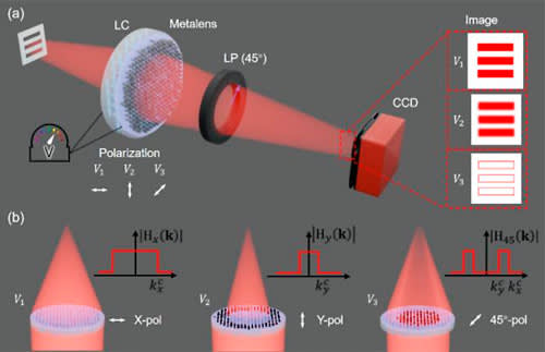
The reported metalens contains rectangular hydrogenated amorphous silicon (a-Si:H) nanopillars on a silica (SiO2) substrate. It has a nominal focal length of approximately 800 μm and two orthogonal, co-focal polarization channels with different effective apertures:
- X-polarized channel: 570 μm effective aperture diameter, approximately 0.336 numerical aperture (NA).
- Y-polarized channel: 120 μm effective aperture diameter, approximately 0.075 NA.
Because the apertures are unequal, the channels pass different ranges of spatial frequencies. Crucially, the nanostructure is also designed to impose a relative phase offset of approximately π radians (180°) in their overlapping pupil region. That phase relationship is essential to the edge-enhanced mode.
Three Imaging States From Two Optical Channels
A voltage-controlled liquid-crystal retarder changes the polarization reaching the metalens, while a polarization analyzer allows the relevant output fields to be combined. The three calibrated states are:
| Input state | Optical response | Role of the channel(s) |
|---|---|---|
| X polarization | Higher-resolution bright-field imaging | Larger effective aperture; wider spatial-frequency passband |
| Y polarization | Lower-resolution bright-field imaging | Smaller effective aperture; narrower spatial-frequency passband |
| 45° linear polarization with 45° analyzer | Interference-synthesized edge enhancement | Coherent combination suppresses overlapping low-frequency information |
In the 45° configuration, both polarization channels are excited. After the analyzer projects their fields onto a common polarization direction, the designed phase offset causes much of their shared low-spatial-frequency content to cancel. Higher spatial frequencies passed by the larger X-channel aperture but not the smaller Y-channel aperture remain comparatively stronger.
In simplified terms, the combined optical response behaves like a spatial high-pass operation. This is coherent interference in the optical field, not subtraction between two photographs after detection. It also means the quality of cancellation depends on the amplitude and phase matching of the two channels.
What the 635 nm Experiments Demonstrated
The research team, involving Pohang University of Science and Technology (POSTECH), the Shanghai Institute of Optics and Fine Mechanics of the Chinese Academy of Sciences, and Korea University, characterized the experimental device at 635 nm. A USAF 1951 resolution target confirmed distinct imaging responses in the two bright-field states and paired bright contours in the edge-enhanced state.
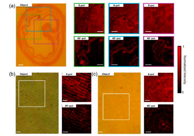
The team also examined an earthworm tissue cross-section, onion epidermal cells and a cross-section of a young Ligustrum stem. In the reported comparisons, optical edge enhancement made some cell and tissue boundaries more conspicuous without applying digital post-processing.
The study reported focal-spot full widths at half maximum of approximately 1.2 μm (X), 4.8 μm (Y) and 1.1 μm (45°) under its measurement conditions. The corresponding focusing efficiencies were approximately 43%, 36% and 24%. These figures characterize this specific experimental system; they are not general performance ratings for metalenses or GIAI optical components.
An additional control device preserved the aperture geometry and focal length but omitted the engineered π-phase relationship. It could still form the two bright-field images, yet it did not reproduce the same edge-enhanced response. This supports the conclusion that the inter-channel phase design, rather than aperture difference alone, is responsible for the demonstrated interference-synthesized mode.
Engineering Trade-Offs: Contrast Is Not Free
Suppressing low-frequency background can improve the visibility of some boundaries, but it does not recover spatial information that the imaging system failed to collect. It can also reduce the optical power reaching the selected image response. The lower measured focusing efficiency in the 45° state partly reflects the deliberate cancellation of shared field components.
Several system conditions are especially important when evaluating this approach:
- Illumination wavelength and bandwidth: the proof-of-concept was optimized for 635 nm. Broadband light can change the phase relationship and weaken the intended cancellation.
- Spatial coherence: interference-based subtraction requires a sufficiently coherent incident field across the channels.
- Polarization preparation and analysis: the liquid-crystal retardance, input polarization and output analyzer must be controlled together.
- Alignment and incidence angle: off-axis incidence, defocus and channel mismatch can alter the optical transfer function.
- Fabrication and transmission losses: deviations in nanostructure geometry or losses in the liquid-crystal and polarizing components can reduce image throughput or contrast.
Accordingly, the result should not be interpreted as a drop-in replacement for digital processing, phase-contrast microscopy or all conventional imaging lenses. It is a specific proof-of-concept architecture for reconfigurable optical image processing.
What This Research Means for Optical System Design
The broader lesson is that image quality is determined upstream of the sensor as well as downstream in software. Light-source spectrum, polarization control, optical transfer function, numerical aperture, transmission losses and detector characteristics must be considered together.
In more conventional imaging and inspection systems, optical filters select or reject wavelength bands, polarizing elements help define polarization states, and optical lenses control image formation and light collection. Those functions are distinct from the specialized metasurface demonstrated in this paper, but they illustrate why component specifications cannot be evaluated independently of the complete optical path.
For example, specifying a filter for a narrowband illumination system may require its center wavelength, usable bandwidth, blocking range, incidence angle and polarization dependence. Likewise, lens selection involves aperture, NA, focal length, aberrations, transmission and mechanical integration. Our Lenses & Optical Components engineering resources discuss how these requirements interact in practical designs.
How GIAI Photonics Fits Into Conventional Imaging Projects
GIAI Photonics supports custom optical component projects involving filters, lenses, prisms, windows, mirrors, beamsplitters and related coated optics. A component’s feasibility and verification requirements are reviewed against the relevant drawing or sample, operating wavelength, substrate, geometry, coating needs, incidence conditions and inspection criteria.
Research-to-product distinction: the polarization-multiplexed metalens and its 635 nm experimental results belong to the cited research team. They must not be understood as a GIAI-manufactured metalens or as evidence of GIAI capability to reproduce the reported device.
If your imaging project needs conventional wavelength-selection or beam-control optics, provide a drawing or specification with the source spectrum, polarization conditions, desired optical function, component dimensions, AOI, inspection method and intended operating environment for project-specific technical review.
Frequently Asked Questions
Does a metalens perform edge detection without artificial intelligence?
In this experiment, yes: the edge-enhancing response arose from an engineered optical interference process before detection. It was not created by AI or digital post-processing. The device still requires a controlled illumination and polarization setup, and it cannot reconstruct information absent from the collected optical field.
Why are there three imaging modes if the metalens contains only two polarization channels?
X and Y polarization separately select two bright-field responses. A third state is synthesized by exciting both channels and combining their fields through a 45° analyzer. Their engineered π-phase relationship reduces shared low-frequency content, creating a qualitatively different transfer function.
Does edge enhancement improve optical resolution in every situation?
No. Edge contrast and spatial resolution are related but different quantities. Suppressing broad background variations can make boundaries more conspicuous without increasing the highest spatial frequency physically collected by the system. Results depend on the target, illumination and optical transfer function.
Can this 635 nm metalens operate over a broad wavelength range?
Broadband operation was not demonstrated for this specific prototype. It was optimized for 635 nm, and changes in wavelength can alter the required relative phase and field matching. Broader-band implementation would require additional dispersion and system-level engineering.
Research References
- Li X. T., Seong J., Kim Y. et al. “Electrically switchable bright-field and interference-synthesized edge-enhanced imaging with a polarization-multiplexed metalens.” Opto-Electronic Science, 5, 260044 (2026). doi:10.29026/oes.2026.260044.
- Compuscript Ltd / EurekAlert!, “Switchable bright-field and edge-enhanced imaging with a polarization-multiplexed metalens,” October 5, 2026. Research news release.
- optics.org, “POSTECH’s electrical lens switches from conventional to edge-enhanced imaging,” October 22, 2026. Industry report.
Editorial note: This article explains independently published optical research. Reported measurements apply to the cited experimental device and should not be interpreted as GIAI Photonics product specifications.