
Technical Resources
Longpass Filter Manufacturer: Specs & Supplier Checks
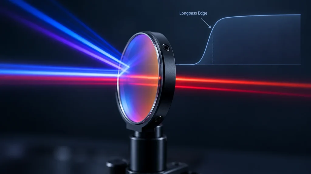
A capable longpass filter manufacturer does more than coat a part to a nominal “LP” number. It agrees with you on how the cut-on wavelength is defined and toleranced, how steep the edge must be, which short-wavelength range is blocked and to what optical density, how far the passband extends, and under which angle of incidence, beam geometry and polarization all of this is measured. Those definitions decide whether the filter works in your system.
A longpass (LP) filter transmits wavelengths longer than its cut-on edge and attenuates shorter ones. The concept is simple, which is exactly why longpass orders go wrong: two filters sold as “LP600” can differ in where 50% transmission falls, how quickly the edge rises, how far down into the blue the blocking actually reaches, and how much the edge moves when the part is tilted in a real optical path. This guide covers what a manufacturer has to control, how to compare suppliers, and what to put in a longpass filter RFQ. For the basic definition, see What Is a Longpass Filter?
What a Longpass Filter Manufacturer Actually Has to Control
Every longpass filter is a trade between three regions of the spectrum: the blocking band on the short side, the transition edge, and the passband on the long side. A supplier is evaluating not one number but how these three regions behave together on your substrate, at your angle, over your detector’s response range.
The construction method sets the starting point. Longpass filters are made in three basic ways, and each one moves the trade-offs differently.
| Construction | How the short side is blocked | Edge behavior | Main engineering risks |
|---|---|---|---|
| Interference (dielectric thin-film) longpass | Multilayer coating reflects the blocked band | Edge can be made steep; position is set by layer design and process control | Finite blocking range; edge shifts to shorter wavelengths with AOI; s/p polarization splitting at oblique incidence |
| Absorptive (colored glass) longpass | Glass absorbs the short-wavelength light | Generally more gradual edge; depends on glass type and thickness | Edge moves with temperature and thickness; some glasses fluoresce under short-wavelength excitation; absorbed energy turns into heat |
| Hybrid (coating on absorbing glass) | Glass provides broad short-side absorption; coating sharpens the edge and adds blocking near it | Steeper than glass alone, with wider blocking than a single coating stack | Combines both sets of dependencies; glass fluorescence and coating AOI shift both need checking |
The choice is application-driven. A detailed comparison of the two mechanisms is in Interference Filter vs Colored Glass Filter.
Longpass Filter Specifications a Manufacturer Must Define
Cut-on wavelength and its tolerance
The cut-on wavelength is usually stated as the wavelength where transmission reaches 50%. The catch is “50% of what.” Some datasheets use 50% absolute transmission; others use 50% of the maximum passband transmission. On a filter with 92% peak transmission, the two definitions land at different points on the edge, and with a gentle edge the difference can be several nanometers.
The product name is not a specification either. “LP600” may refer to the 50% point, to the onset of transmission, or simply to a catalog family. Write the cut-on definition, its nominal value, the tolerance (for example ±x nm) and the measurement AOI into the specification so the supplier’s quotation restates the same thing.
Edge steepness (transition width)
Edge steepness describes how quickly the filter moves from blocking to transmission. It is normally given as the wavelength interval between a blocking point (an OD level or a low transmission value) and a transmission point (for example 90% of maximum), sometimes expressed as a percentage of the cut-on wavelength. Our article on edge steepness in an optical filter covers the definitions in more detail.
A steeper edge is not automatically better. It generally needs more layers or a more complex design, which raises coating time, stress and cost, and it makes cut-on position tolerance and AOI shift more consequential because there is less spectral margin between the light you block and the light you keep. Specify the steepness your source–signal separation actually requires.
Blocking range and optical density
For interference longpass filters, blocking does not extend indefinitely toward short wavelengths. A periodic quarter-wave stack of high-index and low-index layers reflects strongly only over a limited band. In the normalized frequency g = λ0/λ, the full width of that fundamental stop band at normal incidence is approximately:
Δg = (4/π) · arcsin[(nH − nL) / (nH + nL)]As an illustrative calculation, with nH ≈ 2.35 and nL ≈ 1.46 (typical visible indices for titania- and silica-type layers), Δg ≈ 0.30. For a stack designed at λ0 = 500 nm, the stop band spans roughly g = 0.85 to 1.15, or about 435 nm to 590 nm. Below the short end of that band, transmission returns, and quarter-wave stacks also show higher-order reflection bands near λ0/3. Real edge filters use modified designs and material dispersion shifts these numbers, but the principle holds: a single stack blocks a band, not “everything shorter than the edge.”
Manufacturers extend blocking with additional stacks, with absorbing substrates, or by relying on material absorption in the UV. That is why a specification should state the blocking range with both ends, for example “OD ≥ 4 from 400 nm to 580 nm,” and why you should ask what happens outside that range. If your light source emits at 350 nm and the blocking band starts at 400 nm, the datasheet can be correct while the system still sees leakage.
OD should be tied to source power and detector response rather than picked as a round number. See OD4 vs OD6 optical filter blocking for how OD translates into residual signal.
Passband transmission, ripple and the long-wavelength limit
Passband transmission is usually given as an average or minimum value over a stated wavelength range. Edge filters often show ripple near the edge; if your signal sits close to cut-on, a minimum transmission over that region is more meaningful than an average across the whole passband.
Ask where the passband specification ends. On the long side, the limit is set by substrate and coating material transmission, not by the filter name. A filter specified to 1100 nm says nothing about 1550 nm. Uncoated back surfaces matter too: at normal incidence each uncoated glass surface with n ≈ 1.5 reflects about 4%, so a backside AR coating can be part of meeting a transmission target.
Angle of incidence, cone angle and polarization
Tilting an interference filter shifts its spectral features toward shorter wavelengths. A common first-order estimate is:
λ(θ) ≈ λ0 · √[1 − (sin θ / neff)2]Here neff is an effective index that depends on the coating design and differs between s- and p-polarization. Assuming neff = 1.8 purely for illustration, a 600 nm cut-on moves about 2.8 nm shorter at 10° and about 11 nm shorter at 20°. At oblique incidence the s and p edges also separate, so for unpolarized light the edge becomes less steep and the effective blocking near the edge can drop. Converging or diverging beams spread the light over a range of angles and smear the edge in a similar way.
Specify the design AOI, the cone half angle if the beam is not collimated, and the polarization state. Related details are in how polarization affects filter spectra at oblique incidence and cone half angle effects on interference filters.
Substrate, geometry and environment
The substrate must transmit the full passband, survive the coating process, and suit the mechanical design. Thickness affects focus shift in a converging beam, and the clear aperture defines where spectral performance must hold, since edge position can vary slightly across a coated part. For absorptive and hybrid filters, the glass type and thickness also set part of the edge, and the edge position depends on operating temperature. Coating process density affects how much the spectrum can drift with humidity and temperature; if the application runs hot or in changing environments, state the operating range so the supplier can choose the coating approach accordingly.
Application Context Changes the Longpass Specification
The same nominal cut-on can need very different specifications depending on what is being blocked and why.
| Application | What the longpass filter must do | Specification points that usually need attention |
|---|---|---|
| Fluorescence emission | Pass broad emission while rejecting excitation light | Deep OD at the excitation line; edge position versus Stokes shift; glass autofluorescence if colored glass is used |
| Raman spectroscopy | Reject the laser line while passing Stokes-shifted signal close to it | Very steep edge; high OD at the laser wavelength; AOI and beam collimation |
| NIR imaging and machine vision | Suppress visible ambient light while passing NIR illumination | Blocking matched to sensor response; passband covering the illumination band; field angle of the lens |
| IPL and broadband light-source devices | Remove short wavelengths from a high-energy broadband source | Blocking range across the full lamp spectrum; heat handling (reflect vs absorb); coating durability under repeated pulses |
Application-specific guidance: choosing a Raman longpass edge filter, bandpass vs longpass filters for machine vision, choosing fluorescence filters and beauty device filters.
How to Evaluate a Longpass Filter Manufacturer
Supplier comparison should focus on how each manufacturer handles the edge and the blocking band, because that is where longpass filters fail.
1. Does the quotation restate your edge definition?
A good response repeats the cut-on definition, tolerance, edge steepness criteria and measurement AOI in your terms, or explains where its standard definitions differ. A quote that only says “LP600, T > 90%” leaves the important details open.
2. Can the supplier explain how the blocking range is achieved?
Ask whether blocking comes from a single stack, extended blocking stacks, an absorbing substrate or a combination, and what the spectrum looks like beyond the specified blocking range. This tells you whether the short side of your source is actually covered.
3. Are measurement conditions defined?
Spectral verification should state AOI, polarization, beam condition, wavelength range and whether the measured piece is the part itself or a witness sample from the same coating run. High OD values are limited by the photometric range of the measuring setup, so if the specification requires very high blocking, agree on how it will be measured. A curve without its test conditions is not a complete acceptance record.
4. Is edge position controlled across the aperture and between lots?
For applications where a few nanometers of edge shift matter, ask how cut-on uniformity across the clear aperture and lot-to-lot consistency are checked, and what sampling plan applies.
5. Are mechanical and surface requirements inspected against the drawing?
Dimensions, thickness, chamfers, coated area and surface quality are separate acceptance items from the spectrum. Visual appearance does not confirm spectral performance, and spectral performance does not confirm the part meets its drawing.
Common Mistakes When Ordering Longpass Filters
- Ordering by part name (“LP650”) without defining the 50% point, its tolerance and the reference transmission.
- Specifying OD only near the edge while the source also emits much further into the UV or blue.
- Testing at 0° when the filter is mounted at an angle or used in a fast converging beam.
- Ignoring detector response beyond the stated passband, where the filter may no longer be specified.
- Using colored glass in a fluorescence channel without checking whether the glass itself fluoresces under the excitation light.
- Asking for the steepest possible edge when the actual spectral separation would allow a more tolerant design.
What to Send With a Longpass Filter RFQ
| Item | What to specify |
|---|---|
| Cut-on edge | Nominal wavelength, definition (50% absolute or 50% of max), tolerance |
| Edge steepness | Wavelength interval between a stated blocking point and a stated transmission point |
| Blocking | OD and the full blocking range, with both start and end wavelengths |
| Passband | Wavelength range, average and/or minimum transmission, ripple limits if relevant |
| Optical conditions | Design AOI, cone half angle, polarization state |
| System context | Light source spectrum, detector or sensor type, signal wavelength |
| Substrate and geometry | Material (or allowed options), diameter or dimensions, thickness, clear aperture, edge treatment, backside AR |
| Environment | Operating temperature and humidity range; optical power or pulse energy where relevant |
| Acceptance | Measurement method, conditions, sampling, report format |
| Quantity | Prototype, pilot or production volume |
If you are replacing an existing filter, a sample plus its measured curve and the conditions under which it was measured is often the fastest starting point.
Working with GIAI on a Custom Longpass Filter
Longpass filters are part of the GIAI Photonics optical filter range. Custom projects are reviewed against the drawing, sample, spectral requirements, substrate, geometry, coating conditions and inspection criteria before the manufacturing route is defined. Depending on the part, that route can include grinding, polishing, cleaning, edging, optical coating and inspection, as described on our manufacturing capabilities page. Spectral and mechanical verification follow the agreed drawing and specification, as outlined under quality assurance. Values published on individual product pages describe those specific parts, not a general performance limit; feasibility for a new longpass design is confirmed against its own specification. The project steps are summarized in our custom optics process.
FAQ
Is a steeper longpass edge always better?
No. A steeper edge helps when the light to be blocked sits very close to the signal, as in Raman spectroscopy. It usually requires a more complex coating and makes the filter more sensitive to cut-on tolerance and angle shift. When the blocked wavelength and the signal are well separated, a moderate edge with good blocking depth is often the more robust specification.
Can I tilt a longpass filter to tune the cut-on wavelength?
For interference filters, tilting moves the edge toward shorter wavelengths only. The usable range is limited, because the s- and p-polarized edges separate as the angle grows, which reduces edge steepness for unpolarized light and can lower blocking near the edge. If tilt tuning is planned, the filter should be designed and verified for that angle range.
Why does my longpass filter leak light far below the cut-on?
An interference coating blocks a finite band. If the source emits beyond the specified blocking range, light can pass where the coating stack is no longer reflective. Other possible causes are pinholes or coating defects, light bypassing the filter around its edges, and fluorescence generated in a colored glass substrate. Check the source spectrum against the full blocking range first.
How is the cut-on wavelength of a longpass filter measured?
It is usually measured with a spectrophotometer, at a stated angle of incidence and polarization, and read at the agreed transmission level. Results depend on beam collimation and spot position on the part, so both supplier and buyer should use the same definition and conditions. For production, agree whether parts or witness samples are measured and how many.
Can a longpass filter be made to match an existing sample?
Often, yes, but a sample alone does not define the tolerances. Supply the sample together with the parameters that matter in your system: the edge position and tolerance, the blocking range and OD, passband transmission, AOI and dimensions. The replacement is then designed and verified against that specification rather than against a single unit.
References
- H. A. Macleod, Thin-Film Optical Filters, 5th ed., CRC Press, 2018 (quarter-wave stack stop band width, edge filter design, angle and polarization effects).
- R. Paschotta, “Bragg Mirrors,” RP Photonics Encyclopedia (dependence of reflection bandwidth on refractive index contrast).
- SCHOTT, Longpass filter glass overview (absorptive longpass filter terminology).
Planning a custom longpass filter? Send the drawing or sample with the cut-on definition and tolerance, blocking range and OD, passband, AOI and cone angle, substrate, dimensions, operating conditions, inspection criteria and expected quantity for a technical review.
Request a technical review