
Technical Resources
Telecentric F-Theta Lens vs Standard F-Theta Lens
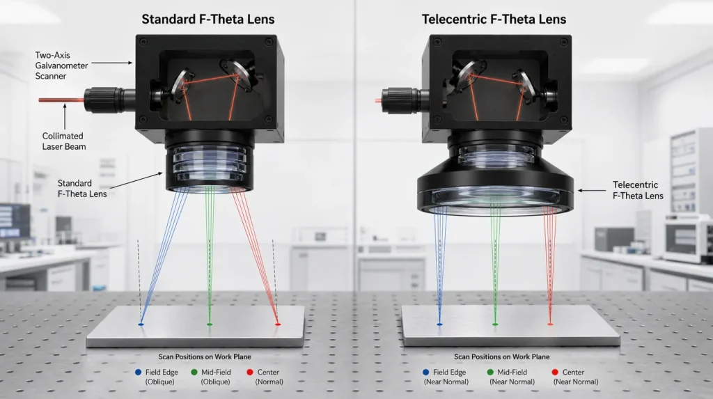
Telecentric F-Theta Lens vs Standard F-Theta Lens: Engineering Differences and Selection
A telecentric F-theta lens vs standard F-theta lens comparison is mainly a question of beam geometry at the workpiece. Both lens types can be designed for a substantially flat scanning field and approximately linear F-theta mapping. The additional requirement in a telecentric design is that the focused beam remains close to perpendicular to the work plane as it moves from the field center toward the edges.
That distinction matters when the laser incidence angle influences hole direction, cut-wall geometry, feature position on surfaces with Z-height variation, or other angle-sensitive processes. For ordinary marking or engraving on a flat surface, however, a standard non-telecentric F-theta lens may provide the required performance with a smaller and less demanding optical package.
What a Standard F-Theta Lens Is Designed to Do
An F-theta lens is a scan objective normally used after a galvanometer or another angular beam-steering system. As the scanner changes the incoming beam angle, the lens focuses the beam at different positions across a nominally flat working plane.
The ideal first-order relationship is:
where y is the displacement of the focused spot from the optical axis, f is the effective focal length and θ is the optical scan angle in radians.
A practical F-theta lens simultaneously has to control several different optical behaviors: field curvature, off-axis aberrations, scan mapping, aperture clearance and spot quality. These parameters are related through the optical design, but they are not interchangeable specifications.
A standard, non-telecentric F-theta lens can therefore have good field flatness and low F-theta distortion while still delivering an increasingly oblique beam at larger field positions.
What Makes a Telecentric F-Theta Lens Different?
A telecentric F-theta lens adds an image-side telecentricity requirement to the scan-lens design. In practical laser-scanning terminology, this means that the axis of the focused beam bundle remains close to the normal of the working plane across the specified scan field.
Real systems normally specify a finite telecentricity error or maximum chief-ray angle rather than assuming mathematically perfect telecentricity.
At the field center, both a standard and a telecentric scan lens may direct the beam almost perpendicular to the workpiece. The difference becomes more obvious toward the edges. In a conventional non-telecentric design, the incidence angle generally increases with field position. In a telecentric design, the optical prescription and aperture geometry are arranged to keep that angle substantially smaller.
Telecentric F-Theta Lens vs Standard F-Theta Lens: Direct Comparison
| Engineering Factor | Standard F-Theta Lens | Telecentric F-Theta Lens |
|---|---|---|
| Primary optical function | Flat-field beam scanning with controlled F-theta mapping | Flat-field scanning plus reduced output chief-ray angle |
| Beam incidence at field edge | Normally becomes increasingly oblique | Maintained closer to perpendicular to the work plane |
| F-theta mapping | Designed around y ≈ fθ | Also designed around F-theta scanning behavior |
| Field flatness | Corrected for a substantially flat working plane | Also requires flat-field correction |
| Optical aperture | Usually more compact for a comparable field | Often requires substantially larger exit-side optics |
| Scan-field packaging | Generally easier to obtain a large field within a limited lens diameter | Large fields can require rapidly increasing lens diameter |
| Sensitivity to workpiece Z variation | Oblique rays can introduce lateral intersection changes when surface height changes | Near-normal chief rays reduce this particular geometric effect |
| Typical process priority | Marking, engraving and general surface processing | Angle-sensitive drilling, cutting and precision structuring |
| System complexity | Usually lower | Typically higher because telecentricity adds another design and alignment constraint |
Why Beam Incidence Angle Matters
Drilling and Deep Features
Consider a laser drilling process near the edge of the scanning field. With a non-telecentric lens, the beam may approach the surface at a noticeable angle rather than along the work-plane normal.
The optical focus may still be correctly positioned on the nominal surface. However, the beam direction through the material is no longer vertical. Depending on process physics, material thickness, focus position and beam propagation, that angle can influence the geometry of the resulting feature.
A telecentric scan lens reduces this angular variation. This is one reason telecentric F-theta optics are considered for micro-drilling, fine cutting and other processes where the direction of energy delivery is part of the tolerance budget.
Surfaces with Height Variation
The difference can also matter when the real surface is displaced from the nominal focal plane.
For an oblique beam, changing the Z position of the intersection surface also changes its lateral intersection coordinate. In a simplified geometric model, the lateral shift increases approximately with the surface-height error and the tangent of the incidence angle.
Reducing the chief-ray angle therefore reduces this particular source of lateral error.
Telecentricity does not, however, eliminate defocus. If a surface moves outside the usable depth of focus, the spot can still enlarge even when the beam arrives perpendicular to the surface. Large three-dimensional height changes may require dynamic focusing, Z-axis motion or another scanning architecture.
Telecentricity and Scan Field Size
One of the most important practical trade-offs is aperture size.
In a standard F-theta lens, beams scanning toward the edge of the field can leave the lens at different angles. In a telecentric system, the lens must redirect those off-axis beam bundles so that they leave toward the workpiece with nearly parallel beam axes.
Supporting this geometry across a large field requires sufficient clear aperture, especially in the elements nearest the workpiece. As the required telecentric scan field increases, the mechanical diameter of these optics can become a major design constraint.
This is why telecentric designs often become larger and more difficult to package than non-telecentric designs covering a similar processing area.
It is therefore unsafe to assume that a telecentric lens with a given focal length will automatically provide the same scan field as a conventional F-theta lens with the same focal length. Actual field size must be checked against the complete optical prescription, scanner geometry, beam diameter and permitted vignetting.
Does a Telecentric Lens Produce a Smaller or More Uniform Spot?
Not necessarily.
Focused spot size depends on wavelength, effective focal length, usable beam diameter, beam-quality factor M², aberrations, aperture truncation and the definition used to report spot diameter.
Telecentricity controls a different property: the direction of the beam bundle at the work plane.
A carefully designed telecentric F-theta lens may also have excellent field-dependent spot performance, but that performance results from the complete optical design rather than from telecentricity alone.
When comparing lenses, request or calculate spot performance at the center, edge and corner of the required field using the intended wavelength and beam diameter. Do not compare only a single minimum spot value.
Telecentricity Is Not the Same as F-Theta Distortion
These specifications are frequently confused.
F-theta distortion describes the deviation between the actual spot coordinate and the ideal F-theta mapping position. It is a positional relationship.
Telecentricity error describes the angular deviation of the chief ray or focused beam axis from the normal to the work plane. It is an angular relationship.
A lens can have low F-theta distortion and still be non-telecentric. Conversely, a telecentric design can still have measurable residual F-theta distortion that requires scanner calibration.
Software correction can compensate for repeatable coordinate errors, but it cannot make an oblique beam physically perpendicular to the workpiece. Optical geometry and coordinate calibration should therefore be treated as separate parts of the system specification.
What About Working Distance?
Telecentricity by itself does not establish whether working distance will be longer or shorter.
Working distance depends on the complete lens prescription, focal length, mechanical housing, protective window and optical configuration. Two scan lenses with similar effective focal lengths can have significantly different mechanical working distances.
For machine integration, verify the manufacturer’s defined reference plane for the working-distance specification. Do not treat effective focal length, back focal length and mechanical working distance as interchangeable dimensions.
When a Standard F-Theta Lens Is Usually Sufficient
A non-telecentric F-theta lens is often appropriate when:
- the workpiece is nominally flat;
- the process occurs mainly at or near the surface;
- moderate variation in beam incidence angle does not affect the feature;
- large scan field is important;
- available lens diameter or scanner packaging is limited;
- the process is conventional laser marking or engraving;
- coordinate errors can be handled through normal scanner calibration.
The correct decision still depends on field size, wavelength, beam diameter, target spot, working distance and process tolerance. “Non-telecentric” does not imply low precision.
When a Telecentric F-Theta Lens Becomes Important
A telecentric design deserves closer consideration when:
- holes must remain close to the surface normal across the field;
- cut-wall or edge angle is tightly controlled;
- the process contains recessed or depth-sensitive features;
- small workpiece-height variations would create unacceptable lateral displacement with an oblique beam;
- the process outcome changes materially with beam incidence angle;
- center-to-edge angular consistency is included in the system tolerance budget.
Even in these cases, telecentricity should be specified quantitatively. The useful requirement is not simply “telecentric lens,” but an acceptable telecentricity error over a defined X-Y scan field and scanner geometry.
Parameters to Compare Before Selecting Either Lens
- Operating wavelength or wavelength range
- CW or pulsed laser operation
- Average power, pulse energy, pulse duration and repetition rate
- Input beam diameter and its definition
- Beam-quality factor M²
- Required X-Y scan field
- Effective focal length
- Optical scan angle
- Galvanometer mirror size and separation
- Lens-to-scanner distance
- Target spot size and field-dependent spot tolerance
- Maximum F-theta distortion
- Maximum field curvature or focal shift
- Required telecentricity error
- Mechanical working distance
- Clear aperture and housing envelope
- AR coating and substrate requirements
Coating performance must also be evaluated under the actual wavelength and angular conditions. High transmission does not by itself establish laser-damage capability. For pulsed lasers, damage assessment additionally depends on pulse duration, fluence, repetition rate, beam profile, coating design, cleanliness and the conditions used for the damage-threshold measurement.
Common Selection Mistakes
Assuming Every F-Theta Lens Is Telecentric
It is not. F-theta mapping, flat-field correction and telecentricity describe different aspects of the optical system.
Choosing Telecentric Optics Simply Because the Process Is Precise
Precision alone is not sufficient justification. First identify whether beam incidence angle contributes materially to the process error.
Comparing Only Focal Length
Two lenses with the same focal length can differ in scan field, clear aperture, working distance, telecentricity, distortion and field-dependent spot behavior.
Assuming Telecentricity Eliminates Z-Axis Problems
It reduces the lateral geometric effect caused by oblique chief rays, but it does not remove defocus when the workpiece leaves the focal region.
Ignoring Scanner Geometry
Telecentric performance is designed around a defined entrance-pupil and scanner arrangement. Changing mirror spacing or scanner-to-lens distance can alter telecentricity, vignetting and usable field performance.
Conclusion
The central difference in a telecentric F-theta lens vs standard F-theta lens comparison is not whether one lens focuses better. Both are scan lenses intended to focus a moving beam over a substantially flat work plane.
The difference is that a telecentric F-theta lens additionally controls the output chief-ray angle so the focused beam remains closer to perpendicular across the field.
That property can be valuable for drilling, cutting, deep structures and other processes where incidence angle or workpiece-height variation influences feature geometry. It also adds optical and mechanical constraints, particularly aperture and lens diameter.
For selection, define the required field, wavelength, beam diameter, spot performance, scanner geometry, working distance, distortion tolerance and allowable incidence angle as one optical-system specification. Telecentricity should be chosen because the process requires it—not because it is assumed to make every F-theta system more accurate.
Frequently Asked Questions
Is a telecentric F-theta lens more accurate than a standard F-theta lens?
Not automatically. Telecentricity primarily controls the angle at which the focused beam reaches the work plane. Positional accuracy also depends on F-theta distortion, scanner calibration, galvo repeatability, lens alignment, field curvature, mechanical stability and manufacturing tolerances. A well-designed standard F-theta lens can provide excellent coordinate performance for surface marking. A telecentric lens becomes advantageous when incidence-angle variation itself contributes to the process or dimensional error.
Is every F-theta lens telecentric?
No. A standard F-theta lens may provide flat-field focusing and approximately linear scan mapping while the beam becomes increasingly oblique toward the scan-field edge. Image-side telecentricity is an additional design requirement that keeps the output chief rays closer to parallel with the optical axis, and therefore closer to perpendicular to a flat workpiece. It should normally be specified by an allowable telecentricity error rather than assumed from the F-theta designation.
Does a telecentric F-theta lens give the same spot size across the entire field?
No. Telecentricity does not guarantee constant spot size. Spot behavior depends on wavelength, input beam diameter, M², effective focal length, lens aberrations, aperture clipping and field position. A telecentric design can also be optimized for good spot uniformity, but the two specifications should be evaluated independently. For demanding applications, compare center, edge and corner spot data under the actual beam and scanner conditions.
Why are telecentric F-theta lenses often larger?
They require sufficient aperture to accommodate beams corresponding to different field positions while redirecting their output axes so they remain close to normal to the work plane. As scan field increases, the required clear aperture of the workpiece-side optical elements can become large. This makes wide-field telecentric scan lenses more demanding in optical diameter, housing size and system packaging than comparable non-telecentric designs.
Do I need a telecentric F-theta lens for laser marking?
Usually not unless the marking process is sensitive to beam incidence angle. Conventional surface marking on a reasonably flat, well-positioned workpiece can often be handled with a standard F-theta lens. Telecentricity becomes more relevant when the application involves deep structures, controlled wall angles, recessed features, workpiece-height variation or other geometry in which an oblique edge-of-field beam creates a measurable process error.
