
Technical Resources
F-Theta Distortion vs Field Curvature in Scan Lenses
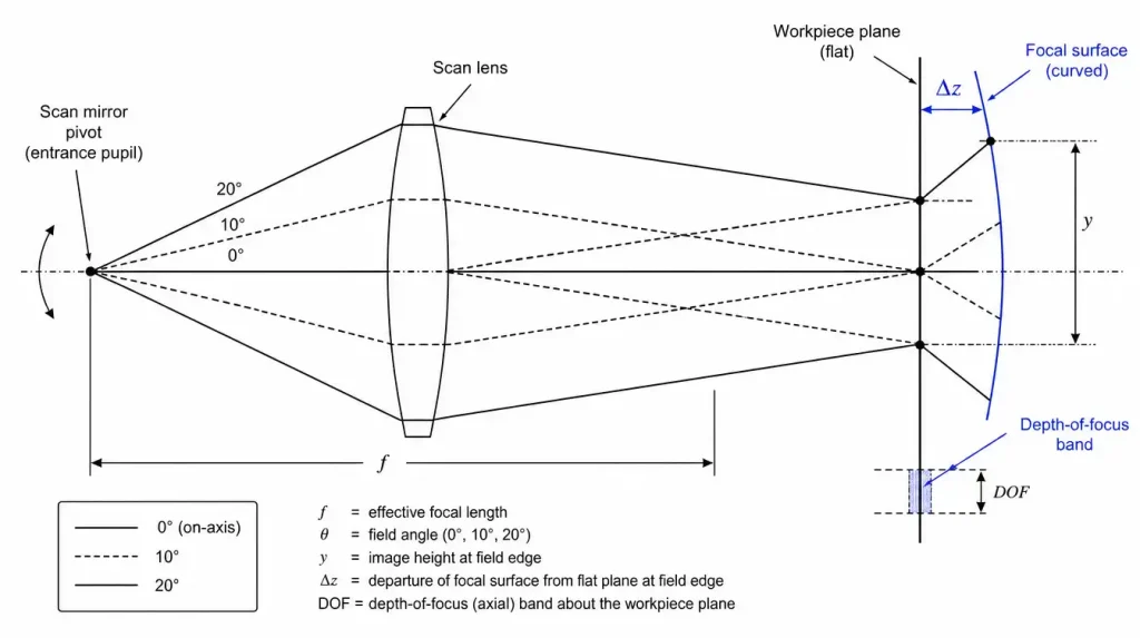
F-theta distortion and field curvature are both field-dependent errors in a laser scan lens, but they fail in completely different ways. F-theta distortion is a position error: the focused spot lands somewhere other than where the scan angle says it should, while staying sharp. Field curvature is a focus error: the spot lands in the right place but sits off the focal surface, so it grows and loses irradiance. The practical consequence of the f-theta distortion vs field curvature distinction is that one is correctable in software and the other is not. You can calibrate distortion out with a correction table. You cannot calibrate a defocused spot back into focus.
That single asymmetry should drive how you weight the two specifications when you select a scan lens.
Why an f-theta lens has distortion by design
A conventional well-corrected lens obeys the tangent condition:
y = f · tan(θ)where y is image height, f is the effective focal length (EFL), and θ is the field angle. That relationship is inconvenient for a galvanometer scanner, because the galvo rotates at a constant angular rate and you want the spot to move at a constant linear rate across a flat workpiece.
An f-theta lens is deliberately designed to the linear condition instead:
y = f · θ (θ in radians)Now a constant angular velocity produces a constant scan velocity, and the drive electronics can command position in angle and get position in millimeters without a nonlinear transform.
Relative to the tangent condition, f·θ is always the smaller image height, so an ideal f-theta lens carries built-in barrel distortion. At a 20 degree optical half-angle:
(θ − tanθ) / tanθ = (0.34907 − 0.36397) / 0.36397 = −4.1%So a perfect f-theta lens is about 4% “distorted” by classical optical standards at the edge of a ±20 degree field. This is the source of most confusion in the f-theta distortion vs field curvature comparison: the intended distortion and the error in that distortion are two different quantities, and the datasheet number refers only to the second.
How f-theta distortion is actually specified
The spec on a scan lens datasheet is the residual deviation from the ideal linear mapping, normalized to ideal image height:
Distortion (%) = 100 × (y_actual − f·θ) / (f·θ)Some vendors publish it instead as an absolute position error in micrometers at the field corner, which is the more useful form when you are budgeting against a part tolerance. Convert before you compare lenses, because 0.3% on a 175 mm field is 260 µm of radial error at the corner, and 0.3% on a 70 mm field is 105 µm.
Commercial scan lenses commonly specify f-theta distortion below 1% of ideal image height, and well-corrected designs are often quoted in the 0.1% to 0.3% range. The number degrades as scan angle and field size increase, so a lens quoted at 0.2% over its rated field will not hold that figure if you push it past the rated scan angle.
The distortion your lens is not responsible for
A two-axis galvo head has two mirrors at two different distances from the lens. The Y-axis pivot sits farther back than the X-axis pivot, and the deflection of the first mirror changes the geometry seen by the second. The result is a pincushion-type warp of the XY grid that exists even with a mathematically perfect f-theta lens, plus a small asymmetry between the two axes.
In practice this scan-head geometry error and the lens distortion are measured together and removed together. You mark a grid on anodized aluminum or coated paper, measure the actual positions on a vision system or CMM, and generate a correction table that the scan controller applies to every commanded position. This is why lens distortion is a soft constraint: a 0.3% lens and a 0.15% lens can produce statistically indistinguishable parts after calibration. What matters is whether the residual error is stable and repeatable, not whether it is small.
Field curvature: the Petzval problem inside a flat-field lens
Field curvature is not correctable this way. The natural image surface of a lens is curved, and the workpiece is flat.
For thin lenses in air, the Petzval sum is:
P = Σ 1 / (n_i · f_i)and the radius of the Petzval surface in image space is R_p = −1 / P. Note that P depends only on element powers and refractive indices, not on how you bend, space, or stop the elements. You cannot remove it by shuffling the layout; you have to introduce negative power in high-index glass, which is exactly what the negative element in a flat-field scan lens is doing.
The scale of the problem is easy to see. An idealized single positive element of n = 1.5 and f = 160 mm has R_p = −240 mm. Over a half-field of 56 mm, the sag of that surface is:
h² / (2·|R_p|) = 56² / 480 ≈ 6.5 mmCompare that to the usable depth of focus. For a Gaussian beam with 1/e² input diameter D, the focused waist and Rayleigh range are:
2w₀ = 4λf / (πD)
z_R = (4/π) · λ · (f/D)²
At λ = 1064 nm, f = 160 mm, D = 10 mm, that gives a 21.7 µm spot and z_R = ±0.35 mm. The single-element field sag is roughly 19 times the depth of focus. Everything outside a small central disk would be badly out of focus. The multi-element flat-field design exists to reduce that 6.5 mm to something comfortably inside ±0.35 mm.
Astigmatism and the “flat” in flat field
Real designs do not drive the Petzval sum to zero. They balance residual astigmatism against it. The tangential and sagittal focal surfaces depart from the Petzval surface in a fixed ratio, with the tangential departure three times the sagittal departure. A designer can leave controlled astigmatism so that the medial surface, the one halfway between tangential and sagittal focus, is flat across the field.
The visible consequence is that the corner spot is often slightly elliptical rather than simply larger. If you are cutting or welding with a directional feature, that ellipticity shows up as a kerf width or seam width that changes with scan direction at the field edge.
How field curvature appears on a datasheet
Scan lens datasheets rarely print a Petzval radius. They express field curvature indirectly, in one of three forms:
- Spot size at field center versus field corner (for example, 21 µm center and 28 µm corner at a stated input beam diameter)
- Focal plane deviation or “field flatness” in millimeters across the rated field
- A through-focus or spot-size-versus-field-position plot
Only the third form tells you the shape of the residual focal surface. If you have a tight process window, ask for the plot. A useful internal rule is to require the focal plane deviation to stay inside about half the Rayleigh range for the beam you actually intend to use, since spot growth is negligible up to roughly that point and rises quickly afterward.
F-theta distortion vs field curvature: side-by-side
| F-theta distortion | Field curvature | |
|---|---|---|
| Physical origin | Residual deviation from the y = fθ mapping | Petzval sum plus residual astigmatism |
| Effect on the spot | None; the spot stays sharp | Spot enlarges, often becomes elliptical at the corner |
| Effect on position | Radial position error, worst at the corner | None directly, unless the lens is non-telecentric |
| Typical datasheet form | % of ideal image height, or µm at corner | Center vs corner spot size, or focal plane deviation in mm |
| How it is measured | Mark a grid, measure with vision system or CMM | Beam profiler on a Z stage, or through-focus spot measurement |
| Correctable after purchase | Yes, with a scan controller correction table | No, except with a dynamic Z focusing module |
| Scales with | Field size and scan angle | Field size, and inversely with lens complexity |
| What it costs you if wrong | Dimensional error on the part | Inconsistent line width, kerf, weld depth, ablation rate |
The trade-offs you are actually buying
Focal length is the master variable. It sets field size, spot size, and depth of focus simultaneously, and you cannot optimize all three.
The table below is calculated for λ = 1064 nm, a 10 mm 1/e² input beam, M² = 1, and a ±20 degree optical half-angle, using the Gaussian relations above. Real lenses deviate because of aberration, truncation at the aperture, and beam quality, so treat these as the diffraction-limited floor rather than a specification.
| EFL | Square field (approx.) | Diffraction-limited spot (1/e²) | Rayleigh range (±) |
|---|---|---|---|
| 100 mm | 70 × 70 mm | 13.5 µm | 0.14 mm |
| 160 mm | 112 × 112 mm | 21.7 µm | 0.35 mm |
| 254 mm | 177 × 177 mm | 34.4 µm | 0.87 mm |
| 420 mm | 293 × 293 mm | 56.9 µm | 2.39 mm |
Reading across: a long focal length buys you field and forgiveness on Z, and costs you spot size and therefore peak fluence. A short focal length buys you resolution and costs you both field and Z tolerance, which is why fine micromachining setups are so sensitive to part flatness and fixturing.
Other trade-offs worth naming:
- Tighter distortion and flatter field cost elements. Both are corrected by adding degrees of freedom. More elements means more surfaces, higher scatter, lower total transmission, and more absorbed power at high average power.
- Telecentric costs aperture. A telecentric scan lens must have a clear aperture at least as large as the scan field, so a 100 mm telecentric lens is a large, heavy, expensive assembly. Non-telecentric lenses stay compact but land the beam at an angle.
- Wider input beam costs depth of focus. Filling more of the entrance aperture shrinks the spot as 1/D but shrinks the Rayleigh range as 1/D², so you tighten the Z tolerance twice as fast as you tighten the spot.
Datasheet parameters to compare, and material notes
When you put two scan lenses side by side, these are the entries that determine whether they are interchangeable:
| Parameter | Why it matters |
|---|---|
| Design wavelength | Scan lenses are corrected for one wavelength or a narrow band; using 532 nm optics at 1064 nm shifts focus and destroys correction |
| EFL and rated scan field | Sets spot size, depth of focus, and working area |
| Maximum optical scan angle | Distortion and field curvature specs are only valid inside it |
| Entrance pupil diameter | Maximum usable input beam; exceeding it vignettes the corners |
| Entrance pupil distance | The design distance from lens to the scan pivot; a mismatch degrades distortion, field flatness, and corner throughput |
| Working distance / back focal length | Fixturing and clearance for the process gas or fume extraction |
| F-theta distortion | % of ideal image height, or µm at corner |
| Spot size center vs corner | The practical proxy for residual field curvature |
| Telecentricity | Chief ray angle at the field edge, if specified |
| AR coating reflectance | Per-surface and total; affects throughput and back reflection into the source |
| Damage threshold | Only meaningful with wavelength, pulse duration, repetition rate, and beam diameter stated, per ISO 21254 |
| Surface quality | Scratch-dig per MIL-PRF-13830B, or the 5/ code per ISO 10110 |
| Surface figure | Typically quoted in waves peak-to-valley at a stated test wavelength |
On materials: N-BK7 and equivalent borosilicate crowns are common at 1064 nm for moderate power. Fused silica is preferred for UV, for ultrashort pulses, and for high average power because of its low absorption, low thermal expansion, and higher damage threshold. Zinc selenide is the standard for CO2 systems at 10.6 µm. Surface quality of 40-20 is common on scan lens elements, with 20-10 or better called out for UV and high-average-power work where scatter and damage initiation matter more.
For designers building around a fixed scan head geometry, GIAI Photonics supplies F-theta lenses along with the optical windows and mirrors that usually sit in the same beam path.
Common specification mistakes
Assuming the ideal mapping is good enough. Skipping calibration and trusting y = fθ bakes the full residual distortion, plus all the two-mirror scan head geometry error, into your parts. The failure is silent: the center of the field is fine and the corners drift out of tolerance. Always mark and measure a grid over the full field before you qualify a process.
Weighting distortion over field flatness. Distortion is the number everyone compares because it is a single tidy percentage. Field curvature is the one you cannot fix later. If you have to choose, choose the flatter field.
Ignoring the entrance pupil distance. This is the most common integration error. The lens is corrected for a specific distance between its first surface and the scan pivot. Mount it on a head with a different mirror separation and you get vignetting at the field corners, degraded distortion, and a focal surface that no longer matches the published curve. The lens is not defective; it is being used outside its design.
Forgetting that a non-telecentric lens couples Z error into XY error. At a 20 degree field edge, the beam arrives at roughly 20 degrees to the surface normal, so a defocus of Δz produces a lateral shift of Δz·tan(20°) ≈ 0.36·Δz. A 0.5 mm part height variation across a fixture becomes about 180 µm of position error at the corner, on top of whatever the distortion contributes. For blind via drilling the same angle produces a tapered, off-axis hole. If your process cares about either, specify telecentric and accept the size and cost.
Filling the aperture without rechecking Z tolerance. Expanding the beam to shrink the spot is a common late-stage tweak. It quarters the depth of focus for a doubling of beam diameter, and a fixture that was adequate before will not be adequate after.
How to choose
Work from the process backward, not from the lens forward.
- Fix the required feature size. That sets the spot, and with your beam quality and input diameter it sets the EFL.
- Check the field. If the required EFL does not cover your part, you either tile the field with a moving stage or move to a dynamic Z focusing module and a larger field.
- Compute the Rayleigh range at that EFL and beam diameter, then compare it against the sum of part flatness, fixture repeatability, and the lens focal plane deviation. If that sum exceeds roughly half the Rayleigh range, the design will not hold across the field.
- Decide telecentricity based on whether Z variation or beam incidence angle affects the process outcome.
- Treat distortion last. It is the one parameter you can still fix in software after the hardware is on the bench.
If step 3 fails and you cannot loosen the spot size, a dynamic focusing module in front of the galvos is the honest answer. It moves focus in Z as a function of field position, which flattens the effective focal surface, extends the usable field beyond what a fixed flat-field lens can cover, and lets you mark on stepped or contoured parts. It adds cost, an extra axis in the correction file, and a settling time that limits mark speed.
FAQ
Is f-theta distortion the same as barrel distortion? No. An ideal f-theta lens has roughly 4% barrel distortion at a ±20 degree field, measured against the tangent condition, and that is intentional. The f-theta distortion on a datasheet is the residual error against the linear y = fθ target, which is a much smaller number. Comparing the two directly is a category error.
Can I correct field curvature with a calibration file? Not with a standard two-axis correction table. That table remaps commanded XY positions and cannot change where the focal surface sits in Z. You need a three-axis system with a dynamic focusing module, where the correction file includes a Z term for each field position. Otherwise the only fix is a better lens or a smaller field.
Why is my spot larger at the corners than at the center? Residual field curvature is the usual cause: the corner of the flat workpiece sits outside the depth of focus. Check by refocusing on a corner point alone. If the spot sharpens, it is field curvature. If it stays large and elliptical at best focus, you are looking at residual astigmatism, coma, or aperture truncation instead.
Do I need a telecentric f-theta lens? Only if the incidence angle or Z sensitivity affects your result. Blind via drilling, deep engraving, and processes on parts with height variation usually justify it. Surface marking on a flat, well-fixtured part usually does not. Telecentric lenses need a clear aperture at least as large as the field, so they get large and expensive quickly.
How much f-theta distortion is acceptable? Convert the percentage to micrometers at your field corner and compare it against your part tolerance. If you calibrate with a grid, most of it disappears and the relevant question becomes repeatability, not magnitude. If you cannot calibrate, budget the raw corner error against tolerance directly and specify accordingly.
Does changing my input beam diameter change the field curvature? It does not change the lens. It changes how much the field curvature hurts. A smaller input beam produces a larger spot and a longer Rayleigh range, so the same focal plane deviation costs proportionally less spot growth. Expanding the beam does the reverse, tightening the Z budget as the square of the diameter change.
Selecting a scan lens is mostly a matter of matching the focal surface and the mapping accuracy to a process you have already characterized, and GIAI Photonics can supply F-theta lenses and the associated coated optics against those requirements.
