
Technical Resources
1064nm F Theta Lens Manufacturer
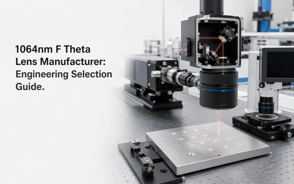
A search for a 1064nm f theta lens manufacturer is usually more than a sourcing request. The lens must be matched to the laser wavelength, beam diameter, galvanometer geometry, scan field, focal-spot requirement, working distance and operating conditions. A lens identified only by “1064 nm” and focal length may fit mechanically while failing to deliver the required edge-of-field focus, positional accuracy or power stability.
What Does “1064nm F-Theta Lens” Mean?
The term combines two separate design requirements.
1064 nm identifies the nominal operating wavelength around which the refractive design and anti-reflection coating are optimized. It is commonly associated with the fundamental output of Nd:YAG lasers and with many ytterbium-doped fiber laser systems. The actual source may have a finite spectral width or operate at a nearby wavelength, so the required operating band should be stated rather than inferred from the nominal wavelength.
F-theta describes the intended relationship between the input scan angle and the position of the focused spot. The lens also controls field curvature and off-axis aberrations so that the moving focus remains usable on a flat processing surface.
“Flat field” does not mean that spot diameter, wavefront quality, incidence angle and irradiance are perfectly constant at every field coordinate. Those characteristics must be specified and evaluated separately.
How an F-Theta Lens Works in a Galvanometer System
A typical post-objective scanning system places the F-theta lens after two galvanometer mirrors. The first mirror deflects the beam along one axis, and the second provides the orthogonal scan. The changing beam angle then enters the lens, which focuses it at a corresponding position on the workpiece.
For an ideal one-axis F-theta system:
In an idealized conventional rectilinear mapping, image height is often written as y = f tan θ. An F-theta design deliberately introduces controlled distortion so that the mapping approaches the more linear fθ relationship. This makes angular scanner commands easier to relate to positions on the processing plane.
The equation remains an approximation. A two-axis scan head has two physically separated mirrors rather than one common pivot point. Mirror separation, entrance-pupil position, lens spacing, residual optical distortion, scanner response and mechanical alignment all affect the final X–Y coordinates.
Optical angle is not mechanical mirror angle
When a reflective galvanometer mirror rotates by a mechanical angle, the reflected beam changes direction by approximately twice that angle. A datasheet specifying ±20 degrees must therefore identify whether it means mechanical mirror rotation or optical beam deflection. Confusing the two can produce an incorrect field-size calculation.
Specifications That Define the Installed Performance
| Parameter | What It Defines | Why It Matters |
|---|---|---|
| Operating wavelength or band | Wavelength range used for optical optimization and coating design | Affects focus, aberrations, transmission, absorption and reflection loss |
| Effective focal length | Focal length measured from the principal plane of the lens assembly | Influences scan field, spot size, depth of focus and system dimensions |
| Input beam diameter | Beam size, preferably with its 1/e² or other stated definition | Affects diffraction-limited spot size, clipping, fluence and scanner aperture |
| Scan field | Usable rectangular, square or circular processing area | Must be stated with scanner geometry, beam diameter and performance limits |
| Optical scan angle | Angular beam range accepted by the scan lens | Works with focal length and aperture to determine the usable field |
| Working distance | Distance from a defined mechanical reference to the nominal work plane | Controls clearance for fixtures, extraction, windows and machine structures |
| F-theta distortion | Deviation from the ideal fθ position | Influences geometric calibration and residual coordinate error |
| Field-dependent spot data | Spot diameter or encircled-energy result at defined field positions | Shows whether edge and corner performance supports the process |
| Telecentricity error | Change in chief-ray angle relative to the work-plane normal | Important for drilling, deep features and angle-sensitive processing |
| Laser operating conditions | CW or pulsed mode, power, pulse energy, duration and repetition rate | Required for thermal and laser-damage assessment |
| Mechanical interface | Housing dimensions, thread, flange and mounting references | Determines scan-head fit and preservation of the designed optical spacing |
Focal Length, Scan Field and Focused Spot Trade-Offs
Longer effective focal length generally produces more displacement for a given scan angle. The approximate one-axis field width may be estimated as:
A longer focal length can therefore support a larger field and greater mechanical clearance. With wavelength and input beam diameter unchanged, however, it also tends to increase the diffraction-related spot size.
For a collimated Gaussian-like beam with negligible truncation and aberration, the focused 1/e² spot diameter can be estimated by:
The installed spot can be larger or asymmetric because of aberrations, lens tolerances, beam clipping, focus error, thermal effects, contamination and field position. Material response, scan speed, pulse overlap and energy density determine the processed feature, so theoretical spot diameter must not be presented as final marking or cutting resolution.
Why the scanner aperture matters
A beam expander can increase the incident beam diameter and reduce the theoretical focal spot, but the expanded beam must fit through the complete scan path. At large mirror angles, an apparently adequate on-axis aperture may clip part of the beam. Clipping can reduce transmitted power, change the focal shape and create different center and edge behavior.
Working distance is not effective focal length
Effective focal length is referenced to the optical principal plane of the assembled lens. Working distance is measured from a specified mechanical surface to the work plane. Back focal length, flange distance, free working distance and effective focal length are not interchangeable. The mechanical drawing must state the reference used.
Standard and Telecentric 1064nm F-Theta Lenses
| Engineering Factor | Standard F-Theta Lens | Image-Side Telecentric F-Theta Lens |
|---|---|---|
| Chief-ray angle | Normally becomes more oblique toward the field edge | Kept closer to perpendicular across the specified field |
| Typical priority | Efficient wide-field marking, engraving and surface processing | Angle-sensitive drilling, cutting or deep-feature processing |
| Optical size | Usually more compact for a comparable field | Often requires a larger final optical element |
| Field implication | Can provide a larger field within a limited package | Field can be constrained by the required exit aperture |
Telecentricity is an additional design property; it is not implied by the name F-theta. It should be specified as a permitted chief-ray angle or telecentricity error under defined field conditions. A telecentric design is not automatically necessary for ordinary surface marking.
Materials, Coatings and Laser-Damage Conditions
Optical glass combinations can provide the refractive-index and dispersion choices needed for aberration correction. Fused silica may be considered for demanding power or short-pulse conditions because of its low thermal expansion and generally low absorption, but material name alone does not establish the performance of the assembled lens.
The transmission range of a bare substrate must not be confused with the performance of the finished, coated assembly. Total throughput also depends on the number of surfaces, coating design, material absorption, surface cleanliness and the actual incidence-angle distribution inside the lens.
A 1064nm anti-reflection coating should be reviewed at the actual wavelength range, polarization and relevant internal angles. High transmission or low reflection does not demonstrate a high laser-induced damage threshold.
For continuous-wave lasers, the review should emphasize average power, coating absorption, mounting, cooling, contamination and thermal focal shift. For pulsed sources, pulse energy, pulse duration, peak intensity, fluence, repetition rate and beam profile become critical. Picosecond and femtosecond sources may also require analysis of spectral bandwidth, chromatic focal shift, internal ghost foci and nonlinear damage mechanisms.
What to Send a 1064nm F Theta Lens Manufacturer
A useful technical review begins with the optical system rather than a request for wavelength and focal length alone. Provide as many of the following inputs as possible:
- Nominal wavelength and operating bandwidth
- CW, nanosecond, picosecond or femtosecond operation
- Average power and maximum pulse energy
- Pulse duration and repetition rate
- Beam diameter and its definition
- M² or beam parameter product
- Beam profile and polarization
- Galvanometer clear aperture
- X–Y mirror separation
- Optical scan-angle range
- Lens-to-scanner distance
- Required X–Y scan field
- Target spot definition and field positions
- Required working distance
- Maximum F-theta distortion
- Telecentricity requirement
- Housing, thread and flange dimensions
- Protective-window configuration
- Workpiece material and process objective
- Environmental and cleanliness conditions
If a requested field, working distance, spot diameter and scanner aperture are mutually incompatible, the optical design may require a larger beam path, different focal length, different galvo aperture or another system architecture. These parameters should not be optimized independently.
Inspection and Acceptance Criteria
Inspection should follow the approved drawing and the characteristics that matter to the installed system. Surface quality, surface figure, transmitted wavefront, centration, parallelism and coating performance describe different properties; one should not be substituted for another.
For an assembled F-theta lens, a practical acceptance plan may include:
- Material and dimensional verification for individual lens elements
- Surface quality, centration, thickness and clear-aperture inspection
- Coating transmission or reflection under agreed wavelength conditions
- Effective focal length and referenced working-distance verification
- F-theta distortion measurement or calculated distortion mapping
- Focus position and spot performance at the center, edges and corners
- Telecentricity measurement when it is a functional requirement
- Mechanical interface, runout and reference-surface inspection
Any quoted spot size should identify the definition used—such as Gaussian 1/e² diameter, Airy diameter, geometrical spot or encircled-energy diameter—together with wavelength, beam diameter, M² and field position.
Applications and Their Different Optical Priorities
| Application | Typical Optical Priorities |
|---|---|
| Laser marking and engraving | Field coverage, spot consistency, working distance, distortion correction and process overlap |
| Laser drilling and micromachining | Small controlled spot, pulse compatibility, low aberration and appropriate telecentricity |
| Laser cutting and welding | Thermal stability, incidence angle, back-reflection control, edge performance and clearance |
| Laser cleaning and surface texturing | Large-area scanning, stable energy delivery, overlap control and contamination management |
An F-theta lens does not independently determine process accuracy, line width or energy uniformity. Laser stability, beam quality, scanner calibration, workpiece height, motion control, material response, contamination and thermal conditions all contribute to the result.
Common Selection Errors
- Selecting only by wavelength: a 1064nm designation does not establish compatibility with the scanner, beam or pulse conditions.
- Comparing focal length alone: lenses with the same focal length can have different fields, apertures, working distances and edge performance.
- Mixing optical and mechanical scan angles: reflective beam deflection is approximately twice the mirror rotation.
- Ignoring mirror spacing: changing scanner geometry can alter vignetting, distortion, telecentricity and ghost positions.
- Treating calibration as optical correction: software can correct repeatable coordinates but cannot repair clipping, defocus or severe aberration.
- Using theoretical spot size as process resolution: actual feature dimensions also depend on energy delivery and material interaction.
- Assuming high transmission means high LIDT: transmission and laser-damage resistance are separate performance questions.
Conclusion
A suitable 1064nm F-theta lens must focus the actual laser beam across the required field while remaining compatible with the galvanometer, mechanical package and operating conditions. The main selection variables are effective focal length, input beam diameter, scanner aperture, mirror spacing, field size, working distance, distortion, telecentricity, coating design and laser power or pulse conditions.
The most reliable procurement approach is to define these requirements together, request field-dependent performance data and establish an inspection plan before production. This separates a lens that merely has a 1064nm coating from one designed for the complete scanning system.
Frequently Asked Questions
Can one 1064nm F-theta lens work with every 1064nm laser?
No. Wavelength matching is only the first compatibility condition. The lens must also be evaluated for beam diameter, M², average power, pulse energy, pulse duration, repetition rate, polarization, scanner aperture, mirror spacing and required field. A lens used successfully with a moderate-power continuous-wave source may not be suitable for a nanosecond or ultrafast source, even when both operate nominally at 1064 nm.
How does focal length affect scan field and spot size?
A longer focal length generally provides more spot displacement for the same optical scan angle and can therefore support a larger processing field. With wavelength and input beam diameter unchanged, it also tends to increase the diffraction-related focal spot and working distance. The final field remains limited by scanner aperture, mirror spacing, lens clear aperture, vignetting and acceptable edge performance.
Does an F-theta lens produce the same spot everywhere?
No. An F-theta lens is optimized to control focus and spot behavior over a specified field, but some field-dependent variation normally remains. The result depends on wavelength, beam diameter, beam quality, aberrations, clipping, manufacturing tolerances and alignment. Spot values should therefore be compared using the same definition and input conditions at the center, edges and corners—not only at the optical axis.
When is a telecentric F-theta lens required?
A telecentric design is useful when the beam must remain close to perpendicular to the work surface across the scan field. This can matter in drilling, cutting, deep structuring and processes in which incidence angle changes feature geometry. Telecentricity is not automatically necessary for surface marking, and the design commonly requires larger exit optics or accepts a smaller field within a given mechanical envelope.
Can calibration eliminate F-theta lens distortion?
Calibration can compensate for predictable coordinate errors produced by the lens, galvanometer response, mirror separation, alignment and controller scaling. It cannot restore optical performance lost to defocus, beam clipping, excessive field curvature, aberration or contamination. Calibration should be carried out using the installed lens, scanner, mounting geometry, controller and actual working plane because these elements behave as one system.
What information should accompany a request for a custom lens?
Provide the wavelength range, laser operating mode, average power, pulse conditions, beam diameter, M², scanner aperture, mirror spacing, optical scan angle, required field, working distance, target spot definition, distortion limit and telecentricity requirement. Mechanical drawings, mounting references, protective-window details, environmental conditions and the intended material process should also be included when available.
