
Technical Resources
Aspheric Lens vs Spherical Lens
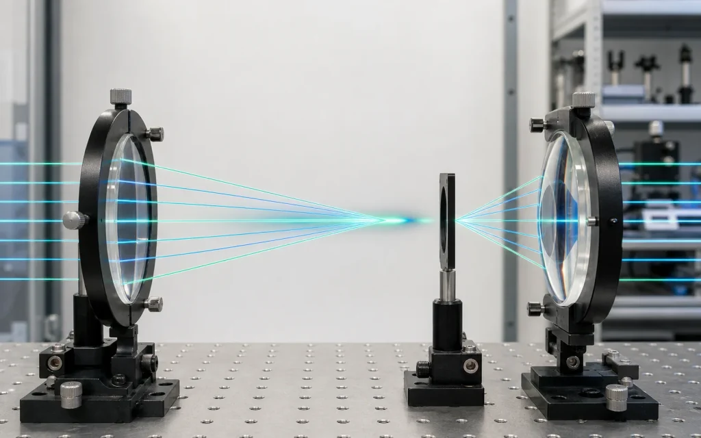
The central difference in an aspheric lens vs spherical lens comparison is surface geometry. A spherical surface has a constant radius of curvature, while an aspheric surface deliberately changes curvature from its optical axis toward its edge. That extra design freedom can reduce spherical aberration and support compact, high-numerical-aperture optical systems. It does not, however, make an aspheric lens automatically superior in every imaging or beam-control application.
What Is a Spherical Lens?
A spherical lens has at least one refracting surface shaped as part of a sphere. Its radius of curvature remains constant across that surface. Common spherical forms include plano-convex, bi-convex, plano-concave, bi-concave and positive or negative meniscus lenses.
Spherical surfaces are widely used because they can be generated, polished and measured with mature optical fabrication methods. Standardized tooling and relatively straightforward interferometric inspection also make spherical lenses suitable for both individual elements and multi-element assemblies.
The limitation is that a spherical surface does not generally bring all rays from an on-axis object point to one identical image point. Marginal rays passing through the outer portion of the aperture are refracted differently from paraxial rays close to the axis. The resulting longitudinal and transverse focus variation is called spherical aberration.
Spherical aberration is not the same as an error in the manufactured radius. It is an inherent behavior of many ideal spherical-surface designs. Its magnitude depends on lens shape, refractive index, focal ratio, aperture, object and image distances, and lens orientation.
What Is an Aspheric Lens?
An aspheric lens contains at least one surface that is not a simple sphere or cylinder. The surface curvature changes with radial distance from the optical axis according to a defined mathematical profile. An asphere may be conic, polynomial, diffractive, freeform or based on another design representation.
A commonly used rotationally symmetric aspheric surface is described by a sag equation containing a base curvature, a conic constant and higher-order coefficients:
In this expression, z is the surface sag, r is the radial coordinate, c is the vertex curvature, k is the conic constant, and the A terms are higher-order aspheric coefficients. The coefficients must be transferred accurately between optical design software, drawings, manufacturing equipment and inspection systems. A sign or normalization error can define a different surface even when the nominal diameter and focal length appear correct.
By changing the refraction of rays across the aperture, an aspheric surface can reduce selected aberrations. In an on-axis collimation or focusing system, it is commonly optimized to bring marginal and paraxial rays closer to the same focus.
Aspheric Lens vs Spherical Lens: Key Differences
| Engineering factor | Spherical lens | Aspheric lens |
|---|---|---|
| Surface profile | Constant radius of curvature across each spherical surface | Curvature varies with radial position according to a defined equation |
| Spherical aberration | Normally remains in a single spherical element, although lens bending or additional elements can reduce it | Can be substantially reduced for the specified wavelength, aperture and conjugates |
| Numerical aperture | Performance can deteriorate as aperture and marginal-ray angles increase | Often better suited to high-NA focusing and light collection |
| Element count | Several spherical elements may be needed to meet an aberration target | One asphere may sometimes replace several spherical surfaces |
| Chromatic aberration | Depends mainly on material dispersion, optical power distribution and system design | Not automatically eliminated; refractive aspheres still exhibit wavelength-dependent behavior |
| Off-axis performance | Can be well corrected in a multi-element design | Depends on the specific design; an on-axis asphere is not automatically optimized for a wide field |
| Manufacturing | Mature grinding, polishing, molding and testing methods | May require precision molding, deterministic polishing, diamond turning or specialized metrology |
| Alignment sensitivity | Often comparatively tolerant, depending on optical power and system architecture | Decenter and tilt may strongly affect performance, especially in fast systems |
| Cost structure | Often economical for standard geometries and moderate volumes | Tooling, form correction and metrology can increase development cost; molding may reduce unit cost at volume |
How Surface Shape Affects Optical Performance
Spherical aberration and focused spot size
In a simple positive spherical lens, marginal rays commonly intersect the optical axis at a different axial location from rays near the center. The detector or target therefore receives a finite blur rather than an ideal point, even if the surface was manufactured exactly to its nominal radius.
Stopping down the aperture reduces the contribution of marginal rays and can improve the spot, but it also reduces numerical aperture and collected optical power. An asphere provides another option: reshape the surface so that rays across a larger clear aperture approach the required wavefront.
The improvement must be evaluated at the system level. A smaller geometric spot does not by itself prove that a lens meets a resolution requirement. Diffraction, wavelength, detector sampling, source size, wavefront error, alignment and working distance also affect the measured result.
Numerical aperture and focal ratio
Numerical aperture describes the angular range over which an optical system accepts or emits light. In air, it is related to the marginal-ray half-angle by NA = sin θ. The focal ratio is approximately related to NA under paraxial conditions, but the approximation becomes less reliable in fast, high-NA systems.
Spherical aberration generally becomes more significant as a spherical lens uses a larger fraction of its aperture. Aspheric lenses are therefore common in laser focusing, diode collimation, illumination collection and compact objectives where high NA is required.
Chromatic and off-axis aberrations
An aspheric surface can be optimized to influence spherical aberration, coma, astigmatism, distortion and field curvature. The actual correction depends on the complete optical prescription rather than the word “aspheric.”
A refractive asphere does not inherently remove chromatic aberration. Refractive index changes with wavelength, so focal length and aberration correction can also change across a spectral band. Broadband systems may still require multiple materials, achromatic combinations or reflective optics.
Similarly, an asphere optimized for an on-axis point source may perform poorly when used at a different object distance or field angle. Wavelength, conjugate ratio, field of view and aperture must match the design conditions.
When an Aspheric Lens Is the Better Choice
An aspheric lens becomes attractive when its additional surface freedom solves a defined system problem. Typical cases include:
- Laser diode collimation: A high-NA asphere can collect a large angular output and reduce on-axis spherical aberration. The diode’s asymmetric divergence may still require cylindrical or anamorphic correction.
- Precision laser focusing: Corrected wavefront error can support a smaller focal spot, provided the input beam, wavelength, clear aperture and alignment match the design.
- LED and illumination systems: An asphere can improve light collection or control the output distribution, although illumination uniformity depends on the full source and system geometry.
- Compact imaging modules: Aspheric surfaces can reduce the number of elements required to control aberrations, helping lower system length, mass or surface count.
- Infrared optics: Aspheres can reduce element count in systems using dense or costly infrared materials. Material transmission, thermal behavior and coating performance remain separate considerations.
- High-NA sensing and microscopy: The design freedom can improve light collection and on-axis image quality where a spherical singlet would produce excessive aberration.
When a Spherical Lens Is the Better Choice
A spherical lens remains an effective engineering choice in many systems:
- The aperture is small enough that residual spherical aberration is acceptable.
- The required resolution is limited by the detector, source or diffraction rather than lens form.
- Several spherical elements can meet the required field and spectral performance.
- The design needs standard sizes, short lead times or multiple sourcing options.
- Simple inspection and interchangeable production tooling are priorities.
- The optical assembly must tolerate a relatively broad range of operating conditions.
- The system requires moderate beam expansion, relay imaging or general focusing without extreme NA.
Lens orientation also matters. For example, a plano-convex lens usually performs better with its curved surface facing the collimated side when focusing a collimated beam. Correct orientation reduces spherical aberration without changing the lens into an asphere.
Manufacturing and Inspection Differences
Spherical surfaces can often be inspected against a reference surface or measured with conventional interferometric arrangements. Radius, center thickness, diameter, centration, surface form and cosmetic condition are relatively familiar production controls.
Aspheric production may use precision glass molding, computer-controlled grinding and polishing, deterministic finishing, single-point diamond turning or injection molding, depending on material, diameter, quantity and accuracy. Each process leaves different possible errors, including mid-spatial-frequency structure, tool marks, edge roll-off, molding shrinkage or departure from the nominal profile.
Asphere metrology must be chosen according to aperture, slope, aspheric departure and required uncertainty. Possible methods include contact or non-contact profilometry, interferometry with a null optic, computer-generated hologram testing, subaperture stitching and transmitted-wavefront measurement. Published metrology research emphasizes that surface-form measurement is a fundamental part of aspheric production rather than an optional final check. [Technical reference](https://www.degruyter.com/document/doi/10.1515/aot-2016-0011/html).
For either lens type, the drawing should not confuse the following specifications:
- Surface quality describes visible defects such as scratches and digs under defined inspection conditions.
- Surface form or irregularity describes deviation from the specified nominal surface.
- Wavefront error describes the optical wavefront after interaction with the component or assembly.
- Centration describes the relationship between optical and mechanical axes.
- Center thickness and edge thickness are dimensional properties, not direct measures of optical form.
Specifications to Define Before Selecting a Lens
- Operating wavelengthSpecify a single wavelength or spectral band and its weighting.
- Object and image conjugatesDefine source distance, target distance and propagation direction.
- Clear aperture and beam diameterDistinguish usable optical aperture from mechanical diameter.
- Numerical aperture or f-numberState whether it applies in object space or image space.
- Focal-length definitionSeparate effective focal length, back focal length and working distance.
- Image-quality targetUse MTF, encircled energy, spot size or wavefront error where appropriate.
- Field of viewDefine field angle, image height and permitted off-axis degradation.
- Surface and centration tolerancesMatch tolerances to actual system sensitivity.
- MaterialConsider refractive index, dispersion, transmission, thermal behavior and environment.
- Coating conditionsDefine wavelength, angle of incidence, polarization and allowable reflection.
An anti-reflection coating can increase transmitted optical power by reducing surface reflection over specified wavelengths and incidence angles. It does not correct surface-form error or geometric aberration. Substrate transmission also does not describe finished-lens transmission because coating, thickness, absorption, scattering and surface reflection contribute to the final result.
Practical Selection Process
- Define the source, wavelength, field, aperture, working distance and detector or target.
- Establish a measurable system requirement such as MTF, spot diameter, wavefront error or collection efficiency.
- Evaluate whether a spherical singlet meets the requirement at the actual aperture and conjugates.
- Compare a multi-element spherical design with an aspheric alternative, including coatings and mechanical packaging.
- Run tolerance analysis for radius or aspheric form, thickness, refractive index, decenter, tilt and element spacing.
- Confirm that the proposed inspection method can verify the performance-critical specifications.
- Test the finished lens in a representative system when source geometry, alignment or environment could affect performance.
The appropriate choice is therefore not based on surface type alone. An asphere may provide better correction with fewer elements, while a spherical design may offer better manufacturability, wider operational tolerance or lower total project risk. The decision should follow the system requirement, tolerance analysis and verification plan.
Frequently Asked Questions
Does an aspheric lens always produce a smaller spot than a spherical lens?
No. An aspheric lens produces a smaller spot only when its prescription matches the wavelength, aperture, input wavefront and object-image conjugates of the application. Manufacturing form error, alignment, source size and diffraction can limit the result. A well-designed multi-element spherical system may outperform a mismatched asphere, especially over a broad field or wavelength range.
Can an aspheric lens eliminate chromatic aberration?
No. A conventional refractive aspheric lens does not eliminate chromatic aberration because the material’s refractive index still changes with wavelength. Its profile may reduce spherical aberration at selected wavelengths and can assist overall correction, but broadband chromatic control normally requires appropriate material selection, multiple optical powers or another system-level correction method.
Can one aspheric lens replace several spherical lenses?
Sometimes. An asphere can replace several spherical surfaces when the main problem is controllable with its added surface degrees of freedom, particularly in compact on-axis systems. Replacement is not guaranteed when the original assembly also corrects chromatic aberration, wide-field coma, astigmatism, distortion or telecentricity. Optical modeling and tolerance analysis are required before reducing the element count.
Why are aspheric lenses more sensitive to alignment?
Many aspheric lenses are used in fast, high-NA systems where small decenter or tilt errors produce significant wavefront changes. The non-spherical profile can also couple alignment errors into asymmetric aberrations. Sensitivity depends on the prescription, so the mechanical datum, edge geometry, centration tolerance and mounting method should be considered during optical design rather than after lens fabrication.
Which parameters should appear on an aspheric lens drawing?
The drawing should define the surface equation and sign convention, vertex radius, conic constant, aspheric coefficients, coefficient normalization, clear aperture, diameter, thickness, material, surface-form tolerance, centration, surface quality and coating. Wavelength and test conditions should accompany optical requirements. A sag or slope table can provide an additional independent check of the intended profile.
Conclusion
The main advantage of an aspheric lens is controlled surface curvature that can reduce selected aberrations and enable high-NA or compact optical systems. The main advantage of a spherical lens is a mature, measurable and often economical geometry that can perform very well when correctly shaped, oriented or combined with other elements.
For engineering selection, compare complete optical prescriptions rather than isolated surface labels. Wavelength, conjugates, field, aperture, material, coating, tolerances, alignment and inspection capability determine whether an aspheric or spherical solution is more appropriate.
