
Technical Resources
Medical Device Optical Filter Manufacturer
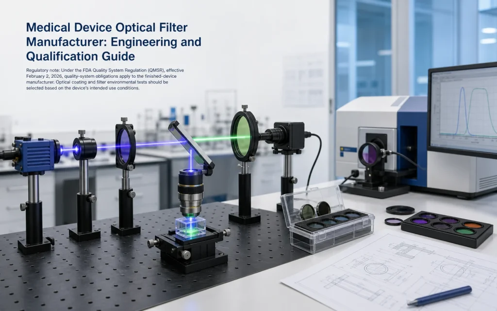
Choosing a medical device optical filter manufacturer is not simply a matter of finding a filter with the correct nominal wavelength. The finished component must work with the device’s light source, detector, optical geometry, operating environment and mechanical assembly. Its performance must also be defined by measurable acceptance criteria that can be applied to prototypes and later production lots.
What Does an Optical Filter Do Inside a Medical Device?
An optical filter selectively transmits, reflects or attenuates parts of the optical spectrum. Depending on its construction, unwanted radiation may be reflected, absorbed or reduced through a combination of both mechanisms. These behaviors should not be treated as interchangeable because they affect stray light, thermal loading and filter placement differently.
In medical and life-science equipment, filters may isolate illumination wavelengths, separate fluorescence emission from excitation light, define a photometric measurement band, suppress ambient radiation, reduce detector saturation or divide an optical path into multiple spectral channels.
The filter supports the optical measurement or imaging process, but it does not independently determine diagnostic accuracy, treatment efficacy or device safety. Those results depend on the complete system, including illumination stability, optics, detector response, electronics, calibration, algorithms, mechanical alignment and operating conditions.
| System type | Possible filter function | Important engineering inputs |
|---|---|---|
| Fluorescence imaging or detection | Separate excitation light from weaker fluorescence emission | Fluorophore bands, source spectrum, detector response, spectral overlap, AOI and blocking |
| Photometric or absorbance analyzer | Define the measurement and reference wavelength bands | Analyte or reagent spectrum, bandwidth, stray light, detector range and channel matching |
| Physiological optical sensing | Isolate LED or laser channels and suppress ambient background | Emitter tolerance, tissue optical path, detector responsivity, ambient spectrum and timing architecture |
| Endoscopic or ophthalmic imaging | Control illumination, color channels, infrared content or fluorescence channels | Image sensor response, color balance, field angle, source power and ghost-reflection control |
| Laser-based medical equipment | Transmit, reject, combine or monitor selected wavelengths | Wavelength, power, beam size, pulse conditions, AOI, polarization and coating durability |
Filter Architectures Used in Medical Optical Systems
Bandpass and narrow bandpass filters
A bandpass filter transmits a defined spectral region while attenuating wavelengths on both sides. A narrow bandpass filter performs the same basic function with a comparatively smaller bandwidth. These filters are frequently considered for fluorescence, photometry and spectrally selective sensing.
The center wavelength alone is not enough to define a bandpass filter. Engineers should also state the full width at half maximum, passband transmission, blocking range, optical density and measurement conditions.
Longpass and shortpass filters
A longpass filter transmits wavelengths longer than its transition region, while a shortpass filter transmits shorter wavelengths. These edge filters can separate broad spectral regions and may be combined with other filters to create a defined transmission window.
The cut-on or cut-off value must be tied to a stated transmission level. A transition specified at 50% transmission is not equivalent to a wavelength at which the filter merely begins to transmit.
Dichroic filters and mirrors
A dichroic component separates light mainly by wavelength-dependent transmission and reflection. In an epi-fluorescence path, for example, a dichroic mirror can reflect the excitation band toward the sample while transmitting longer-wavelength emission toward the detector.
Dichroic components are commonly used at non-normal incidence, often around 45 degrees. Their spectral behavior must therefore be evaluated at the intended angle and polarization condition rather than inferred from a normal-incidence spectrum.
Neutral-density filters
A neutral-density filter reduces optical intensity without intentionally selecting one narrow wavelength band. However, real filters are not perfectly spectrally neutral over every wavelength. The attenuation range, spectral uniformity, reflection and absorption characteristics should be defined for the application.
Specifications to Send a Medical Device Optical Filter Manufacturer
A technically useful request begins with the optical system rather than a filter name. The following parameters establish a practical basis for design review and quotation.
1. Operating wavelength and spectral bands
For a bandpass filter, specify the required passband, center wavelength and bandwidth. For an edge filter, define the transmission and blocking regions on both sides of the transition. For a dichroic filter, specify both the reflected and transmitted bands.
Where possible, provide the actual source spectrum and detector responsivity. A detector may remain sensitive far beyond the nominal signal wavelength, so a narrow blocking statement near the passband may leave important leakage regions uncontrolled.
2. Transmission requirement
State whether transmission is a minimum value at every wavelength, an average across a band or a peak value. Peak transmission describes the highest point and can conceal lower performance elsewhere in the usable band. Average transmission is more representative for some broadband applications, but it does not ensure a minimum at every wavelength.
3. Blocking and optical density
Optical density describes attenuation on a logarithmic scale:
Here, T is fractional transmission rather than percentage transmission. An OD of 4 corresponds to a transmission of 0.0001, or 0.01%, at the specified wavelength.
An OD value without a wavelength range is incomplete. “OD 4 blocking” should identify where that blocking applies and whether the requirement is an average or minimum value. The requested OD must also be compatible with the available measurement method and instrument noise floor.
4. Angle of incidence and beam geometry
The angle of incidence, or AOI, is the angle between the incoming ray and the surface normal. Multilayer interference filters generally shift toward shorter wavelengths as incidence angle increases. At oblique incidence, differences between s- and p-polarized light can also become significant.
A filter installed in a converging beam does not experience one AOI. Different rays reach the coating at different angles, which may broaden or distort the effective system passband. Provide the nominal AOI, angular range, cone angle or numerical aperture when relevant.
5. Substrate and coating structure
The substrate affects mechanical strength, thermal behavior, refractive index, thickness options and intrinsic transmission. Its bulk transmission range does not automatically describe the finished coated filter. The complete component spectrum includes the effects of the substrate, coating stack, surface reflections, absorption and any cemented or laminated interfaces.
Coating selection should consider the required spectrum, AOI, polarization, temperature range, humidity, cleaning method and anticipated exposure to abrasion or chemicals. Environmental testing should be chosen according to the real use condition rather than added as a generic list.
6. Mechanical and surface requirements
Define the external dimensions, thickness, tolerances, clear aperture, edge treatment and orientation marks required for assembly. Surface quality, flatness, parallelism, wedge, total thickness variation and transmitted wavefront error describe different properties and should not be used as substitutes for one another.
- Surface quality addresses visible surface imperfections such as scratches and digs.
- Flatness describes deviation of an optical surface from an ideal plane.
- Parallelism or wedge describes the angular relationship between two surfaces.
- Total thickness variation is the difference between measured maximum and minimum thickness.
- Transmitted wavefront error describes how the complete component changes the wavefront passing through it.
An imaging system may need wavefront, wedge or ghost-reflection control that would be unnecessary for a non-imaging detector placed close to the filter.
How to Evaluate a Medical Device Optical Filter Manufacturer
The evaluation should determine whether the manufacturer can convert the device requirement into a manufacturable and inspectable component definition. A polished sample with an attractive spectrum is useful, but repeatable production requires additional controls.
Review measurement conditions, not only spectral plots
Two spectral measurements can differ because of wavelength resolution, beam divergence, spot size, polarization, AOI, reference correction or instrument stray light. A graph without test conditions may be unsuitable for acceptance decisions.
The drawing or inspection agreement should identify the properties that will be measured, the test geometry and the acceptance rule. If every production part will not receive a complete spectral scan, the sampling plan and lot-level reporting should be defined by the device manufacturer’s risk and supplier-control process.
Separate optical-component qualification from medical-device approval
Certificates should be checked for issuer, validity, scope and relevance. A general certificate or material declaration should not be interpreted as evidence that a particular filter meets its spectral drawing or that the assembled device meets medical performance requirements.
Prototype and Production Validation
A practical qualification sequence progresses from specification review to component measurement and finally to system-level verification.
- Define the optical function. Identify what the filter must transmit, reflect, attenuate or separate within the device.
- Establish acceptance bands. Convert target curves into measurable passband, blocking, edge, AOI and dimensional requirements.
- Review manufacturing feasibility. Confirm substrate, coating concept, size, tolerance and inspection capability before freezing the drawing.
- Measure prototypes. Compare supplied samples with the agreed spectral and mechanical requirements.
- Test the assembled optical path. Evaluate signal level, background, channel crosstalk, image effects, thermal behavior and alignment sensitivity in the actual device.
- Freeze the approved configuration. Record the approved drawing revision, material, coating requirement, orientation and acceptance method.
- Define production controls. Establish the required inspection records, sampling, lot identification, deviation handling and change-notification process.
A witness sample can be useful for coating-run monitoring, but it is not automatically identical to every finished part. Differences in substrate, position within the coating chamber, geometry and subsequent processing should be considered when deciding how witness data will be used.
Common Specification Mistakes
- Requesting only a nominal wavelength without passband width or tolerance.
- Using peak transmission when minimum or average transmission is what the system requires.
- Giving an OD value without its applicable wavelength range.
- Applying a normal-incidence curve to a filter used at 45 degrees.
- Ignoring polarization behavior at oblique incidence.
- Assuming substrate transmission is the same as finished-filter transmission.
- Specifying surface quality when flatness, wedge or transmitted wavefront is the actual imaging concern.
- Treating high reflectivity as proof of a high laser-damage threshold.
- Qualifying a sample without defining how later production lots will be accepted.
- Assuming the filter alone determines device accuracy or clinical performance.
FAQ
What information should I send to a medical device optical filter manufacturer?
Send the optical function, source wavelength or spectrum, detector response, passband, blocking range, required optical density, AOI, polarization condition, substrate, dimensions, clear aperture and operating environment. Include a drawing when available. It is also helpful to identify whether the filter is located in a collimated, converging or diverging beam because angular distribution can change the effective spectral response of an interference filter.
Which filter type is normally used for medical fluorescence detection?
Fluorescence systems commonly use an excitation filter, a dichroic beam-separating element and an emission filter. The exact combination depends on the excitation source, fluorophore absorption and emission spectra, detector sensitivity and optical geometry. Because the emitted signal may be much weaker than the excitation light, out-of-band blocking and spectral separation can be as important as peak transmission.
How much optical density does a medical filter need?
There is no universal OD requirement for medical optical filters. The necessary blocking depends on the unwanted source intensity, detector responsivity, permissible background, integration time and complete optical path. OD must always be specified over a wavelength range. Excessively demanding blocking can increase coating complexity and inspection difficulty without improving system performance if other stray-light paths dominate.
Why must angle of incidence be included in the filter specification?
Angle of incidence must be included because interference-filter spectra change with operating angle. Increasing AOI generally shifts spectral features toward shorter wavelengths, and oblique incidence may produce different responses for s- and p-polarized light. If the filter operates in a converging beam, the full angular range should be considered rather than specifying only the central ray angle.
Does an optical filter supplier need to approve the finished medical device?
No. The optical filter supplier manufactures and verifies a component against agreed requirements, while the finished-device manufacturer remains responsible for system design, risk management, supplier controls, validation and regulatory compliance. The required supplier documentation depends on the component’s role and the applicable quality process. A component certificate should not be presented as approval of the complete medical device.
Final Engineering Considerations
Selecting a medical device optical filter manufacturer is ultimately a specification, measurement and production-control decision. The strongest starting point connects the source, optical path, filter, detector, mechanical assembly and operating environment.
A useful filter definition states what must be transmitted, reflected or blocked; where the spectral limits apply; how AOI and polarization are handled; which dimensional and surface properties matter; and how prototypes and production lots will be evaluated. This approach gives engineers and procurement teams a consistent technical basis for comparing samples without attributing complete device performance to a single optical component.
