
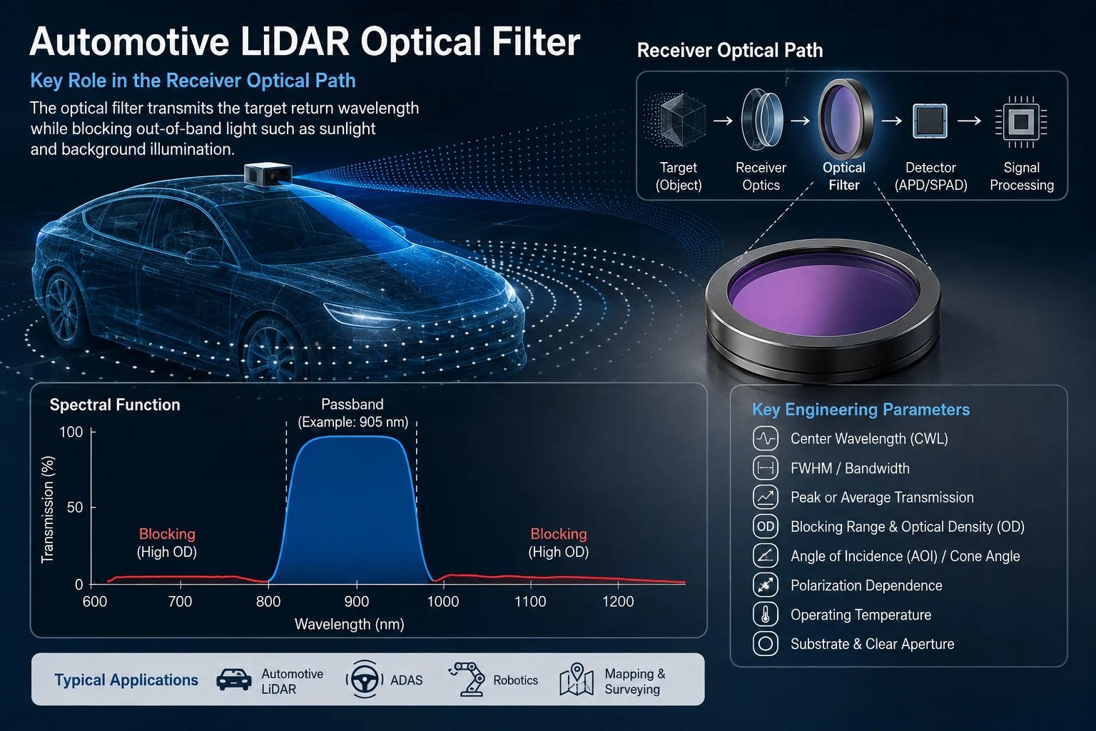
An automotive LiDAR optical filter manufacturer should be evaluated by how well the filter specification matches the complete receiver, not simply by whether a catalog filter is labeled 905 nm or 1550 nm. Automotive LiDAR receivers must distinguish weak returned laser energy from sunlight and other optical background while operating across real field angles, source tolerances, temperatures, mechanical constraints, and detector characteristics. A bandpass filter can contribute to wavelength selection and background suppression, but it cannot independently determine detection range, ranging accuracy, point-cloud quality, or vehicle-level reliability.
For engineering qualification, wavelength, FWHM, transmission, blocking range, optical density, angle of incidence, polarization, substrate, clear aperture, environmental conditions, and inspection criteria need to be treated as one connected specification.
What Does an Optical Filter Do in Automotive LiDAR?
In a typical LiDAR receiver, the optical filter is positioned in the receiving path before the photodetector or detector assembly. Its basic purpose is to transmit the wavelength region containing the wanted laser return while attenuating selected wavelengths outside that region.
This matters because the receiver does not collect only reflected laser light. It may also receive sunlight, artificial illumination, stray reflections, optical crosstalk, and radiation entering through the receiver field of view. Experimental automotive LiDAR work identifies solar background illumination as an important contributor to false detections and receiver noise.
A suitable narrow bandpass filter can therefore reduce part of the unwanted optical energy reaching the detector while preserving the intended return band.
The simplified optical chain is:
laser source → target → receiver optics → optical filter → detector → electronics and signal processing
The filter is only one element in this chain. Final performance also depends on emitted optical power, target reflectance, receiver aperture, detector response, optical alignment, electronics, algorithms, atmospheric conditions, and ambient illumination.
Automotive LiDAR Filters Should Not Be Specified by Wavelength Alone
Automotive LiDAR systems do not use one universal operating wavelength. Research and deployed architectures include systems around 905 nm as well as systems around 1550 nm, with the appropriate wavelength depending on laser architecture, detector technology, optical design, and system requirements.
GIAI Photonics currently lists filter examples associated with both 905 nm and 1550 nm laser-ranging applications. These should be treated as application examples rather than universal automotive specifications.
For a real project, engineers should define more than a nominal wavelength:
- source center wavelength;
- source spectral width;
- wavelength tolerance;
- temperature-related source shift;
- expected production variation;
- detector spectral response;
- required filter passband;
- operating AOI and angular distribution.
A filter centered at the nominal laser wavelength under one laboratory condition may not maintain the required overlap with the source under every installed operating condition.
905 nm and 1550 nm Require Different System Context
Both approximately 905 nm and 1550 nm architectures appear in automotive LiDAR development, but a filter manufacturer should not treat them as interchangeable versions of the same component.
A 905 nm design must be matched to the source spectrum, receiver optics, detector response, field of view, and required background rejection of that system.
A 1550 nm design likewise needs its own substrate, coating, detector, bandwidth, angular, and environmental evaluation. Research on 1.5 µm automotive LiDAR sources specifically considers narrowband receiver filtering as part of controlling ambient solar radiation.
The engineering question is therefore not:
“Is 905 nm or 1550 nm better?”
It is:
“What passband and blocking characteristics does this particular source–receiver–detector architecture require across its actual operating conditions?”
Center Wavelength and FWHM Must Be Defined Together
For a bandpass optical filter, the center wavelength describes the approximate spectral center of the transmission region. Full width at half maximum, or FWHM, describes the bandwidth between the two wavelengths where transmission reaches half of the passband maximum.
Neither specification should be considered independently.
A narrower FWHM can reduce part of the broadband background reaching the detector. However, an excessively narrow passband can become problematic if the laser wavelength, coating response, temperature, or incidence angle shifts enough that the useful return moves toward or outside the effective transmission band.
Consider this simplified hypothetical specification:
| Parameter | Illustrative Requirement |
|---|---|
| Nominal laser wavelength | 905 nm |
| Filter center wavelength | Defined from source and receiver requirements |
| FWHM | Defined after wavelength and angular tolerance analysis |
| Passband transmission | Minimum or average value over a stated interval |
| Blocking | Defined over specified wavelength regions |
| AOI | Nominal angle plus expected angular range |
| Polarization | Defined where relevant |
| Temperature | Defined according to system validation conditions |
These values are illustrative only and are not GIAI Photonics measured product specifications.
The design objective is not simply the narrowest possible filter. It is sufficient useful-signal transmission combined with appropriate rejection of unwanted optical background.
Why AOI Is Especially Important in Automotive LiDAR
Angle of incidence, or AOI, is one of the most important specifications for interference filters used in LiDAR receivers.
Thin-film interference filters are inherently angle dependent. Changing the incidence angle changes the optical phase conditions in the multilayer stack, and conventional interference bandpass filters generally shift spectrally as incidence angle changes. Research uses this angle-dependent behavior of interference filters directly for optical angle detection, demonstrating that the spectral response and incident angle are physically linked.
An automotive receiver rarely consists of a single perfectly collimated ray striking a filter at exactly 0°.
Depending on the optical architecture, the filter may receive:
- on-axis rays;
- off-axis field rays;
- converging light;
- a finite cone angle;
- different field angles across the receiver;
- rays affected by scanning or steering optics.
Wide-field LiDAR experiments also demonstrate receiver architectures that combine a defined field of view with optical bandpass filtering, illustrating why filter performance must be considered within the receiver geometry rather than only at normal incidence.
Therefore, specifying only a 0° spectral curve may be insufficient.
The manufacturer should ideally receive the nominal AOI together with the expected minimum and maximum incidence angles or sufficient optical information to understand the angular distribution at the filter.
Cone Angle Can Matter as Much as Nominal AOI
A filter may be nominally mounted perpendicular to the optical axis and still experience a distribution of incidence angles.
For example, when a filter is located inside a converging receiver beam, rays near the edge of the cone strike the multilayer coating at a different angle from the chief ray.
The resulting system response can effectively become a combination of multiple angle-dependent spectra rather than one laboratory spectrum.
Useful information may include:
- receiver f-number;
- numerical aperture where appropriate;
- field of view;
- filter position relative to the lens;
- chief-ray angle;
- maximum cone angle;
- clear aperture.
This is one reason why optical filters for wide-field sensing applications should be evaluated with receiver geometry in mind.
Polarization Should Be Checked at Significant AOI
At normal or near-normal incidence, polarization differences may be relatively small for many filter designs. At more oblique incidence, S- and P-polarized light can exhibit different spectral behavior because multilayer interference conditions differ for the two polarization states.
Research into optical filters at oblique incidence specifically addresses the challenge of maintaining non-polarizing behavior as incidence angle increases.
For an automotive LiDAR project, the specification should therefore state whether performance is evaluated using:
- unpolarized light;
- S polarization;
- P polarization;
- or a defined system polarization state.
This becomes increasingly important when receiver geometry creates substantial incidence angles.
Blocking Must Be Defined by Wavelength Range
Optical density is commonly expressed as:
OD = −log10(T)
where T is fractional transmittance.
For example, an OD4 blocking region corresponds to:
T = 10⁻⁴ = 0.0001 = 0.01% transmission
However, stating only “OD4” or “OD5” is incomplete.
The required blocking wavelength range must also be defined.
A useful automotive receiver specification may identify different blocking requirements across different wavelength regions depending on:
- detector responsivity;
- ambient solar spectrum;
- neighboring optical sources;
- other active sensors;
- internal stray-light paths;
- receiver optics.
Deep blocking also needs an inspection method with sufficient measurement dynamic range. A requested OD value is only meaningful if the agreed test method can verify it.
Peak Transmission Is Not Enough
A high peak-transmission number may look attractive, but it represents only the highest point of the passband.
It does not describe:
- transmission over the full useful laser spectrum;
- transmission at angular extremes;
- transmission at temperature extremes;
- passband shape;
- spectral edge position;
- lot-to-lot variation.
For some applications, minimum transmission across a specified wavelength interval is more informative than peak transmission.
For others, average passband transmission may be appropriate.
The drawing or optical specification should clearly state which definition is being used.
Match Blocking to the Detector Response
The photodetector determines which incoming wavelengths can contribute significantly to the electrical signal.
The required blocking spectrum should therefore be evaluated together with the detector response rather than selected independently.
Useful inputs for the filter manufacturer can include:
- source spectrum;
- detector responsivity curve;
- ambient-light assumptions;
- receiver aperture;
- field of view;
- optical cone angle;
- filter location.
Published LiDAR receiver experiments demonstrate the use of a 905 nm bandpass filter directly in front of a detector to reduce unwanted optical background, reinforcing the importance of treating the filter and detector as part of the same receiver chain.
Automotive Applications Add Environmental Variables
An automotive optical component is not evaluated only under one room-temperature spectral measurement.
Depending on the intended installation and project requirements, validation may need to consider changes associated with:
- operating temperature;
- thermal cycling;
- humidity or condensation risk;
- contamination;
- vibration;
- mechanical stress;
- adhesive or retaining structures;
- window reflections;
- assembly tolerance.
These conditions should not automatically be converted into a generic “automotive-grade” specification.
Instead, the customer and manufacturer should define the actual qualification conditions required for the component and assembled optical system.
Temperature deserves particular attention because the source spectrum, coating response, substrate, mechanical assembly, and detector can all respond differently to temperature changes. The relevant engineering requirement is the performance of the complete optical chain over the specified operating condition, not merely the room-temperature center wavelength.
Substrate and Coating Must Be Evaluated as One Component
A LiDAR filter is not only a thin-film coating.
The substrate also influences:
- transmission;
- thickness;
- flatness;
- mechanical strength;
- thermal response;
- surface quality;
- packaging;
- clear aperture.
The transmission range of an uncoated material must not be treated as the transmission curve of the finished filter.
Finished spectral performance depends on the substrate, multilayer coating, surface reflections, AOI, polarization, and measurement conditions.
When a filter also acts as an external or internal protective window, mechanical and environmental requirements become even more relevant.
Clear Aperture Is Not the Same as Part Size
External dimensions tell the manufacturer how large the component is.
Clear aperture defines the optical region over which the required performance must be maintained.
They are not necessarily identical.
Mounting areas, bevels, edge exclusion, coating fixtures, retaining rings, adhesive zones, and mechanical structures can reduce usable optical area.
A part may therefore fit mechanically while still failing to provide sufficient optical aperture for the receiver.
Both overall dimensions and clear aperture should be shown on the engineering drawing.
What Should an Automotive LiDAR Filter Manufacturer Measure?
A meaningful spectral report should identify the conditions under which the data were obtained.
Depending on the specification, inspection information may include:
| Requirement | Inspection Information |
| Passband | Wavelength interval and transmission definition |
| CWL | Measurement condition and tolerance |
| FWHM | Defined method |
| Blocking | Wavelength regions and OD requirement |
| AOI | Measurement angle |
| Polarization | S, P, unpolarized or defined state |
| Clear aperture | Tested optical area |
| Surface requirements | Defined drawing criteria |
| Dimensions | Mechanical tolerances |
| Environmental validation | Agreed project conditions |
A spectrum measured at normal incidence should not automatically be used as proof of performance at a substantially different installed angle.
Likewise, a center-point measurement does not necessarily characterize spectral uniformity across a large working aperture.
Prototype Qualification Should Come Before Production Acceptance
Filter inspection and LiDAR system validation answer different questions.
A filter spectrum verifies optical-component performance under the stated measurement conditions.
System testing determines whether the complete receiver works adequately with that component.
Representative prototypes may therefore need evaluation under relevant combinations of:
- ambient illumination;
- field angle;
- target reflectance;
- distance;
- temperature;
- alignment;
- receiver optics;
- transmitter-to-receiver crosstalk;
- mechanical assembly;
- contamination.
Automotive LiDAR research shows that detection performance depends strongly on photon budget, receiver architecture, target and environmental variables, including solar background.
The optical filter can contribute to controlling background reaching the detector, but it should not be described as independently guaranteeing LiDAR range, accuracy, sensitivity, or reliability.
Engineering Checklist for Evaluating an Automotive LiDAR Optical Filter Manufacturer
Before comparing filter samples or quotations, define the engineering problem first.
| Parameter | What Should Be Defined |
| Laser wavelength | Nominal wavelength, spectrum and tolerance |
| Temperature behavior | Relevant source and system variation |
| CWL | Required spectral position |
| FWHM | Required usable bandwidth |
| Transmission | Peak, minimum or average |
| Blocking | OD plus wavelength ranges |
| AOI | Nominal angle and angular range |
| Cone angle | Receiver beam geometry |
| Polarization | S, P, unpolarized or defined |
| Detector | Spectral response |
| Substrate | Material and thickness |
| Clear aperture | Working optical area |
| Dimensions | Mechanical envelope and tolerances |
| Surface requirements | Only as required by optical function |
| Environment | Project-specific operating conditions |
| Inspection | Spectral, dimensional and cosmetic criteria |
| Prototype validation | Agreed sample and system test conditions |
| Production acceptance | Lot and inspection requirements |
This provides a much stronger basis for evaluating an automotive LiDAR optical filter manufacturer than comparing center wavelength and peak transmission alone.
What Information Should Engineers Provide?
For an automotive LiDAR receiver project, a useful technical package can include:
- LiDAR architecture and application;
- laser wavelength and source spectrum;
- wavelength tolerance and temperature behavior;
- detector response;
- desired passband;
- required FWHM;
- minimum or average transmission;
- blocking wavelength ranges;
- required optical density;
- nominal AOI;
- angular range or cone angle;
- polarization condition;
- filter position in the receiver;
- dimensions and thickness;
- clear aperture;
- substrate preference, if defined;
- surface and wavefront requirements where necessary;
- environmental conditions;
- mechanical drawing;
- inspection and acceptance requirements.
GIAI Photonics provides infrared filters, bandpass filters, and narrow bandpass filter products, including current catalog examples associated with 905 nm and 1550 nm laser-ranging applications. Specific automotive suitability should still be established from the actual system specification, drawing, prototype evaluation, and agreed inspection conditions rather than inferred from a wavelength label alone.
Final Engineering Considerations
Selecting an automotive LiDAR optical filter manufacturer is fundamentally a specification and qualification task.
The important question is not whether a supplier can produce a filter marked “905 nm” or “1550 nm.” The filter must maintain adequate useful-signal transmission across the real source spectrum and receiver angles, provide defined blocking over relevant detector-sensitive wavelengths, fit the mechanical package, and be measurable against agreed acceptance criteria.
The most useful specification connects:
source → receiver geometry → filter → detector → environment → inspection
When wavelength, bandwidth, transmission, blocking, AOI, polarization, substrate, clear aperture, temperature conditions, and inspection methods are defined together, prototype and production results can be evaluated on an objective engineering basis.
For projects involving nonstandard wavelengths, narrow spectral requirements, defined cone angles, special dimensions, substrates, or mechanical integration, engineers may provide wavelength requirements, drawings, source and detector data, operating conditions, samples, and inspection requirements to GIAI Photonics for component evaluation.
FAQ
What optical filter is normally used in automotive LiDAR?
A bandpass or narrow bandpass interference filter is commonly used in the receiver when the system needs to transmit a defined laser-return wavelength while reducing selected out-of-band optical background. The correct filter depends on the laser spectrum, detector response, receiver field of view, AOI, cone angle, polarization, and environmental conditions. Experimental LiDAR receivers commonly incorporate wavelength-selective bandpass filters ahead of the detector.
Is 905 nm the standard wavelength for automotive LiDAR?
No. Approximately 905 nm is widely used in automotive LiDAR architectures, but automotive LiDAR systems also operate around 1550 nm and other wavelengths depending on source, detector, and system architecture. The filter specification should follow the actual laser and receiver design rather than assuming one universal wavelength.
How narrow should an automotive LiDAR filter be?
There is no universal optimum FWHM. A narrower passband can reduce some broadband optical background, but it still has to transmit the useful laser return after accounting for source tolerance, temperature behavior, filter manufacturing tolerance, AOI, and receiver cone angle. The appropriate bandwidth therefore comes from a system tolerance analysis rather than selecting the smallest available number.
Why is angle of incidence important for a LiDAR bandpass filter?
Because interference-filter spectra depend on incidence angle. Different rays in a wide-field or converging LiDAR receiver may strike the filter at different angles, creating different effective spectral responses across the beam. Engineers should therefore specify nominal AOI together with the expected angular range or cone angle rather than relying only on a normal-incidence spectrum.
What OD is required for an automotive LiDAR filter?
OD cannot be specified meaningfully without a wavelength range. The necessary blocking depends on the detector response, ambient spectrum, receiver architecture, allowed background level, and other optical sources. Engineers should define both the required OD and the wavelength interval over which it applies, together with AOI and measurement conditions.
What should be tested before approving a LiDAR filter for production?
First verify the component against the agreed spectral, dimensional, surface, and mechanical requirements. Then evaluate representative samples inside the assembled receiver under relevant field angles, illumination levels, temperatures, targets, alignment conditions, and mechanical tolerances. Component inspection establishes filter performance; it does not by itself establish complete LiDAR system performance.