
Technical Resources
How to Choose a Wavefront Error Specification for Optical Components
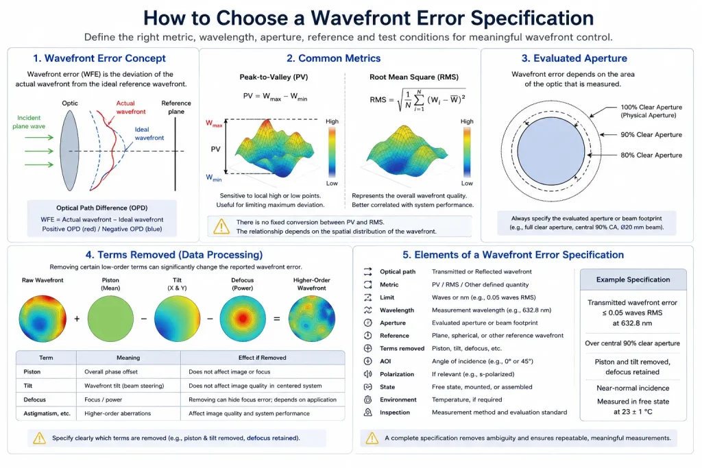
Knowing how to choose a wavefront error specification means defining more than a number such as λ/4 or λ/10. A complete specification should identify what wavefront is being controlled, whether the limit is PV or RMS, the reference wavelength, the evaluated aperture, which low-order terms are removed, and the relevant test conditions. The required tolerance should come from the optical system’s performance budget rather than from a habitual catalog value. A window, filter, mirror, individual lens and complete lens assembly can require very different limits even when they operate at the same wavelength.
Wavefront deformation describes the departure of the actual transmitted or reflected wavefront from the desired wavefront. Formal optical drawing practice treats transmitted and reflected wavefront deformation as defined optical characteristics rather than simply as another name for surface flatness.
What Does a Complete Wavefront Error Specification Need to Define?
At minimum, an engineering wavefront specification should answer these questions:
- What component or assembly is being measured?
- Is the requirement for transmitted or reflected wavefront?
- Is the limit expressed as peak-to-valley, RMS, or another defined quantity?
- What measurement wavelength is used?
- What aperture or beam footprint is evaluated?
- What reference wavefront is expected?
- Which terms, such as piston, tilt or defocus, may be removed?
- At what angle of incidence is the optic tested?
- Is the optic measured unmounted, mounted, or in both conditions?
- Are temperature, polarization or other operating conditions relevant?
Without these conditions, a statement such as “wavefront error ≤ λ/4” is incomplete because different test methods and data-processing choices can produce different reported values for the same optic.
First Decide What You Are Actually Controlling
The first step is to distinguish surface form from wavefront performance.
Surface form describes the departure of an optical surface from its intended geometry. Wavefront error describes the resulting optical path deviation of light relative to the intended wavefront.
They are related, but they are not interchangeable.
For a transmissive component, transmitted wavefront error can be affected by:
- front-surface form;
- rear-surface form;
- thickness variation and wedge;
- refractive-index inhomogeneity;
- coating-induced deformation;
- mounting stress;
- temperature gradients;
- the optical test configuration.
Therefore, specifying surface flatness alone does not necessarily define the transmitted wavefront performance of an optical window.
For reflective optics, the relationship between surface displacement and reflected optical path is also different from the relationship for transmitted optics. An optical mirror should therefore be specified according to the reflected beam requirement rather than by copying a transmitted-wavefront tolerance from another component type.
For optical lenses, the relevant quantity may be the transmitted wavefront of an individual element, a cemented group or the fully assembled optical system.
The specification must identify which level is actually linked to system performance.
PV or RMS: Which Wavefront Error Metric Should You Use?
Two of the most common quantities are peak-to-valley (PV) and root mean square (RMS) wavefront error.
For a wavefront function (W(x,y)), PV is conceptually:
PV = maximum wavefront deviation − minimum wavefront deviation
RMS represents the statistical magnitude of the wavefront variation over the evaluated aperture:
RMS = √[mean((W − mean W)²)]
PV is easy to understand because it captures the largest difference between the highest and lowest points in the wavefront map. However, it can be strongly influenced by a small localized defect or measurement outlier.
RMS considers the entire evaluated wavefront and is often more useful when relating distributed aberration to optical-system performance or constructing a wavefront error budget.
There is no universal conversion factor between PV and RMS. Two wavefronts with identical PV values can have very different RMS values and very different spatial distributions of aberration. Optical engineering references therefore caution against assuming a fixed PV-to-RMS ratio.
For many precision applications, specifying RMS together with a clearly defined aperture and term-removal convention provides a more reproducible performance description. PV can still be useful where maximum departure is important or where established manufacturing drawings use PV limits.
In demanding systems, both may be specified, but only when each limit serves a clear engineering purpose.
Always State the Reference Wavelength
A wavefront specification expressed in fractions of a wave has no complete physical meaning unless the wavelength is defined.
For example, the following two statements are not equivalent:
- λ/4 at 632.8 nm
- λ/4 at 1064 nm
As a simplified conversion:
Physical OPD = wavefront error in waves × reference wavelength
Therefore:
λ/4 at 632.8 nm = approximately 158 nm PV
This is only an illustrative conversion, not a recommended tolerance.
The same physical optical-path error represents a larger fraction of a wave at shorter wavelengths. This is why the reference wavelength must appear on a drawing or inspection specification whenever wave units are used.
For greater clarity, some engineering specifications state wavefront error directly in nanometers RMS or nanometers PV while also identifying the measurement wavelength.
Define the Evaluated Aperture
Wavefront error depends on the area of the optic that is measured.
A component might satisfy a requirement over an 80% clear aperture but fail the same numerical requirement when almost the entire physical aperture is included.
The specification should therefore define the evaluation region, for example:
- full clear aperture;
- central 80% clear aperture;
- central 90% clear aperture;
- a specified circular beam diameter;
- the actual system beam footprint.
The correct choice depends on how the component is used.
If a 25 mm window is used with only a 10 mm collimated beam, controlling the entire 25 mm optical surface to an extremely tight transmitted-wavefront requirement may provide little system benefit. Conversely, an imaging system that uses nearly the full aperture cannot assume that the central region represents the entire optic.
The aperture definition should therefore follow the real optical path wherever practical.
Specify Which Terms May Be Removed
Wavefront data are commonly decomposed into lower- and higher-order aberration components. Depending on the measurement and application, data processing may remove terms such as:
- piston;
- tilt;
- defocus or power;
- astigmatism;
- other explicitly defined aberration terms.
This matters because removing a term can substantially reduce the reported RMS or PV value.
Tilt is normally separated from wavefront deformation in formal optical drawing definitions.
Defocus requires more application-specific judgment.
If the final optical system has an adjustable focus mechanism, it may be reasonable in some cases to evaluate residual wavefront after removing defocus. If the component must preserve collimation or there is no available focus compensation, removing defocus during inspection could hide an error that matters in the finished system.
A specification should therefore state the permitted removals explicitly rather than relying on the default settings of the interferometer software.
For example:
TWE ≤ 0.05 waves RMS at 632.8 nm over 90% CA, piston and tilt removed, defocus retained.
That is far less ambiguous than simply writing:
TWE ≤ λ/20.
Consider Angle of Incidence and Polarization
Wavefront measurements are often made close to normal incidence, but the installed optic may operate at another angle.
For a simple uncoated isotropic component, polarization may have little influence on the geometric surface-error contribution. For coated optics operating at significant angle of incidence, however, optical phase behavior can depend on wavelength, angle and polarization.
The mechanical beam footprint also changes with incidence angle.
If the real application operates at a defined non-zero AOI, especially for filters, beamsplitters, mirrors or other coated components, the engineering team should determine whether the wavefront requirement needs to be verified at or correlated with that operating condition.
Do not automatically assume that a normal-incidence interferometric result completely represents performance at 45° or another system angle.
Account for Mounting and Environmental Conditions
An optic can meet its wavefront requirement in a free-state measurement and perform differently after installation.
Mechanical preload, uneven retaining contact, adhesive shrinkage, thermal-expansion mismatch and housing deformation can modify surface form, alignment or internal stress. GIAI Photonics’ existing discussion of lens mounting stress therefore distinguishes free-state inspection from mounted-state system performance.
For wavefront-sensitive applications, consider whether the specification should apply:
- before coating;
- after coating;
- in the free state;
- after installation in the intended mount;
- at a defined operating temperature;
- across a required environmental range.
Not every project needs all of these tests. The inspection state should reflect the dominant system risk.
Do Not Choose λ/4 or λ/10 by Habit
One of the most common specification mistakes is selecting a familiar fraction of a wavelength without connecting it to the complete optical system.
The correct process runs in the opposite direction:
System performance requirement
→ total allowable wavefront error
→ error budget
→ component allocations
→ manufacturing and inspection tolerances
The system requirement might be expressed through image quality, MTF, spot size, Strehl ratio, beam quality, interferometric accuracy or another application-specific metric.
The optical designer then determines how much wavefront degradation can be allocated to:
- residual optical design aberration;
- optical fabrication;
- refractive-index variation;
- alignment;
- mechanical mounting;
- thermal effects;
- coating deformation;
- assembly;
- measurement uncertainty.
Component wavefront tolerances can then be assigned from that budget.
For statistically independent RMS contributions, root-sum-square budgeting may sometimes be appropriate, but independence, common normalization and consistent apertures must be justified. PV values should not simply be combined using the same assumption.
This approach prevents both under-specification, which risks system performance, and over-specification, which can make manufacturing and inspection unnecessarily difficult.
Simplified Wavefront Specification Examples
The following values are hypothetical specifications provided only to show how complete callouts can be written.
Example 1: Plane-Parallel Window
Transmitted wavefront error ≤ λ/4 PV at 632.8 nm over central 90% clear aperture, near-normal incidence, piston and tilt removed.
This callout defines the optical path being evaluated, metric, wavelength, aperture and permitted data processing.
Example 2: Higher-Precision Transmissive Component
Transmitted wavefront error ≤ 0.05 waves RMS at 632.8 nm over a 20 mm circular aperture, piston and tilt removed, defocus retained.
At 632.8 nm, 0.05 waves corresponds to approximately 31.6 nm RMS.
Again, this is an illustrative value rather than a general recommendation.
Example 3: Mounted Optical Assembly
Assembly transmitted wavefront error ≤ 60 nm RMS at 632.8 nm over the defined entrance pupil, after final mechanical assembly, piston, tilt and focus removed.
This type of requirement may be more useful when the final system performance depends on interactions among several elements rather than any one optical surface.
How Should Wavefront Error Be Written on a Drawing or Specification?
A practical callout should identify the following information in one location or through clearly referenced drawing notes:
| Specification Item | What to Define |
|---|---|
| Optical path | Transmitted or reflected wavefront |
| Metric | PV, RMS or other defined quantity |
| Limit | Waves, nm or another appropriate OPD unit |
| Wavelength | Measurement or reference wavelength |
| Aperture | Clear aperture or defined beam footprint |
| Reference | Plane, spherical or other intended wavefront |
| Removed terms | Piston, tilt, defocus, etc. |
| AOI | Test or operating incidence angle if relevant |
| Polarization | When optically relevant |
| Mechanical state | Free, mounted or assembled |
| Environment | Temperature or other conditions if required |
| Inspection | Defined measurement and evaluation method |
The objective is not to make the drawing complicated. It is to remove ambiguities that could otherwise allow two laboratories to report different results while both believing they have followed the same specification.
Modern wavefront metrology commonly relies on interferometric techniques, while other measurement methods can also be used where appropriate. Current measurement standards explicitly address interpretation of both optical surface form and system wavefront-deformation data.
Common Wavefront Specification Mistakes
Writing only “λ/4”
The wavelength, PV/RMS metric, aperture and measurement conditions remain undefined.
Confusing surface flatness with transmitted wavefront error
A transmissive component’s final wavefront can depend on both surfaces, material properties, thickness variation, coatings and mechanical stress.
Assuming PV and RMS have a fixed relationship
The relationship depends on the spatial shape of the aberration and cannot be represented by one universal conversion factor.
Ignoring the measured aperture
Wavefront results obtained over different apertures should not be assumed equivalent.
Removing defocus without considering the application
If the system cannot compensate focus, removing defocus may hide a functionally important error.
Applying the same tolerance to every component
A protective window, precision imaging lens, beam-expanding optic and interferometer reference optic do not require identical wavefront performance.
Ignoring the mounted condition
A free-state component measurement does not necessarily predict the final optomechanical assembly when mounting stress is significant.
Technical Conclusion
A useful wavefront specification is not defined by choosing the smallest possible fraction of a wavelength. It is defined by connecting the optical system’s performance requirement to a measurable component or assembly tolerance.
Engineers should first decide whether transmitted or reflected wavefront is the relevant characteristic, then define PV or RMS, wavelength, aperture, permitted term removal and test conditions. Mechanical mounting, coatings, operating angle and environment should be included when they can materially change the result.
Most importantly, wavefront tolerance should be derived from the system error budget rather than copied from a standard catalog specification.
For projects involving nonstandard apertures, demanding imaging or laser requirements, unusual operating conditions or drawing-defined tolerances, engineers may provide wavelength requirements, drawings, dimensions, operating conditions and inspection requirements to GIAI Photonics for component evaluation.
FAQ
What is a good wavefront error specification?
There is no universal wavefront error value that is appropriate for every optical component. A suitable specification depends on wavelength, aperture, system performance, whether the optic is transmissive or reflective, and how much of the system error budget can be allocated to that component. Instead of starting with λ/4 or λ/10, determine the allowable system wavefront degradation and derive the component tolerance from that requirement.
Is RMS or PV better for specifying wavefront error?
RMS is generally more informative about the wavefront across the complete evaluated aperture, while PV describes only the difference between the maximum and minimum values. PV remains widely useful for manufacturing specifications, but it can be strongly influenced by localized extrema. There is no fixed conversion between PV and RMS, so the required metric should be stated explicitly rather than converting one to the other using a constant ratio.
Why must wavelength be specified with wavefront error?
A wave is a wavelength-dependent unit. A physical optical-path difference of 100 nm represents a different fraction of a wave at 532 nm than at 1064 nm. Therefore, a requirement such as λ/10 is incomplete unless the reference wavelength is known. Stating the limit directly in nanometers can reduce ambiguity, but the measurement wavelength should still be documented.
Is surface flatness the same as transmitted wavefront error?
No. Surface flatness describes the form of an individual optical surface, while transmitted wavefront error measures the combined optical-path distortion introduced as light passes through the component. For a transmissive optic, both surfaces, thickness variation, material inhomogeneity, coating effects and mechanical stress may contribute to the transmitted wavefront.
Should wavefront error be measured before or after mounting?
The correct inspection state depends on the application. Free-state testing is useful for verifying the optical component itself, while mounted-state testing evaluates the combined behavior of the optic and its mechanical support. In systems sensitive to mounting preload, adhesive stress or temperature-dependent deformation, comparing both conditions can help separate component errors from assembly-induced effects.
