
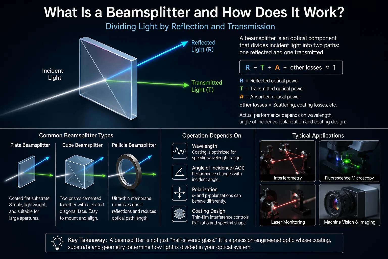
What is a beamsplitter and how does it work? A beamsplitter is an optical component that divides incident light into two main optical paths: one reflected and one transmitted. In many designs, this is achieved with a partially reflective optical coating deposited on a transparent substrate or positioned inside a prism assembly.
The division does not have to be equal. A beamsplitter may be designed for a nominal 50:50, 30:70 or another reflection-to-transmission ratio, or it may separate light according to polarization or wavelength. Actual performance depends on wavelength, angle of incidence, polarization, coating design, substrate and other operating conditions.
How Does a Beamsplitter Split Light?
A conventional beamsplitter works through controlled reflection and transmission at an optical interface.
When light reaches an interface between materials with different refractive indices, some light can be reflected while some continues through the interface. Optical thin-film coatings allow this behavior to be engineered much more precisely.
Instead of allowing the natural Fresnel reflection of an uncoated glass surface to determine the result, a beamsplitter coating uses multiple thin-film layers or another partially reflective coating structure to control how much optical power is reflected and how much is transmitted.
The result can be represented by:
R = reflected optical power / incident optical power
T = transmitted optical power / incident optical power
For a simplified low-loss system:
R + T ≈ 1
In a real optical component, absorption, scattering and other losses may also exist, so a more complete power balance may be written conceptually as:
R + T + A + other losses ≈ 1
where A represents absorption.
This is why a nominal 50:50 beamsplitter should not automatically be interpreted as exactly 50% reflection and exactly 50% transmission under every possible condition.
What Does a 50:50 Beamsplitter Actually Mean?
A 50:50 specification normally means that the component is designed to divide optical power approximately equally under defined conditions.
Those conditions matter.
A meaningful beamsplitter specification should identify parameters such as:
- wavelength or wavelength range;
- angle of incidence;
- polarization condition;
- allowed reflection and transmission tolerance;
- substrate;
- clear aperture;
- environmental or laser conditions when relevant.
A coating optimized for a certain wavelength and incidence geometry may behave differently when either is changed.
The same issue applies to polarization. At oblique incidence, s-polarized and p-polarized light generally do not interact with an interface in exactly the same way. A coating can be designed to reduce this difference, exploit it deliberately, or accept it when polarization is unimportant.
Therefore, the statement “50:50 beamsplitter” is incomplete without test and operating conditions.
Why Angle of Incidence Matters
Angle of incidence, usually abbreviated AOI, is the angle between the incoming beam and the surface normal.
Many plate beamsplitters are designed for operation around a specified oblique angle because the reflected beam must be separated spatially from the transmitted beam. A 45° configuration, for example, produces a convenient right-angle relationship between the incident and reflected paths.
Changing AOI can change:
- reflectance;
- transmittance;
- spectral response;
- s/p polarization balance;
- phase response;
- beam geometry.
This behavior follows from the angle dependence of optical interference and Fresnel reflection.
For broadband or polarization-sensitive systems, the cone angle can also matter. A converging or diverging beam contains a range of incidence angles rather than one single AOI, so different rays may experience slightly different coating responses.
Performance should therefore be evaluated using the actual beam geometry rather than assuming that a normal-incidence specification applies unchanged at an oblique angle.
Why Polarization Matters
At oblique incidence, light is commonly resolved into two orthogonal polarization components:
s-polarization has its electric field perpendicular to the plane of incidence.
p-polarization has its electric field parallel to the plane of incidence.
Their Fresnel reflection coefficients differ, so ordinary coatings can produce different reflection and transmission values for s and p polarization.
This leads to three important beamsplitter categories.
Standard Beamsplitters
A standard beamsplitter is designed primarily around an optical power splitting ratio.
It may be suitable when the incoming light is unpolarized and small polarization differences are not critical to system performance.
However, engineers should not assume that a standard 50:50 beamsplitter provides exactly the same 50:50 ratio independently for s and p polarization.
Non-Polarizing Beamsplitters
A non-polarizing beamsplitter is designed to reduce the difference between its response to s- and p-polarized light within a specified wavelength and AOI range.
“Non-polarizing” does not mean that polarization physics disappears. It means the coating is designed so the specified R/T performance of the two polarization components remains sufficiently similar for the intended application.
The allowable difference between s and p response should therefore be defined when polarization balance is important.
Polarizing Beamsplitters
A polarizing beamsplitter intentionally treats the two polarization states differently.
A common configuration is designed to transmit predominantly p-polarized light while reflecting predominantly s-polarized light.
These components are used when optical power must be separated according to polarization rather than simply divided according to intensity.
When polarization control is part of a larger system, the beamsplitter may operate together with other polarizing filters or polarization-control optics.
Plate Beamsplitters
A plate beamsplitter typically consists of a flat optical substrate with a beamsplitting coating on one surface.
The incoming beam reaches the coated surface at an oblique angle. One portion is reflected and the remainder passes through the substrate.
Plate construction offers several practical advantages:
- relatively thin optical structure;
- lower weight than a comparable solid cube;
- potential suitability for larger clear apertures;
- relatively short optical path through glass.
However, plate geometry introduces engineering considerations.
The transmitted beam refracts when entering and exiting the substrate and can therefore experience lateral displacement. The rear surface can also generate an unwanted secondary reflection.
For this reason, the back surface is often given an anti-reflection treatment, and some plates use a small wedge to separate residual ghost reflections from the main beam.
Parallelism, wedge, substrate thickness, flatness and mounting stress may all become relevant in imaging or interferometric systems.
Cube Beamsplitters
A cube beamsplitter is commonly constructed from two right-angle prisms assembled together, with the beamsplitting coating located at the internal diagonal interface.
Light typically enters approximately normal to an external cube face. It then reaches the internal beamsplitting interface, where part of the beam is transmitted while another part is reflected through approximately 90°.
Compared with a plate design, a cube can simplify mechanical integration and reduce some beam-displacement issues.
However, light travels through substantially more optical material.
That additional optical path can matter when the system involves:
- converging or diverging beams;
- chromatic effects;
- ultrashort pulses;
- thermal effects;
- high optical power;
- wavefront-sensitive imaging.
The material, assembly method and coating must therefore be matched to the actual system rather than selected only from the physical convenience of the cube shape.
What Is a Pellicle Beamsplitter?
A pellicle beamsplitter uses an extremely thin optical membrane instead of a conventional glass plate.
Because the membrane is extremely thin, the separation between front- and rear-surface reflections is very small. This can help minimize the secondary ghost image that can occur with thicker parallel plates.
Pellicles also introduce relatively little glass into the optical path.
The tradeoff is mechanical robustness. Thin membranes are significantly more delicate than conventional glass substrates and may be unsuitable for systems where contamination, handling, pressure changes or mechanical exposure are difficult to control.
Pellicle construction is therefore useful in certain optical layouts but is not a universal replacement for plate or cube designs.
How Is a Dichroic Beamsplitter Different?
A conventional intensity beamsplitter divides optical power within a selected wavelength range.
A dichroic beamsplitter is primarily designed to separate light by wavelength.
For example, a coating may be designed to reflect one spectral region while transmitting another. Thin-film interference determines the spectral transition between the reflected and transmitted bands.
This makes dichroic components closely related to wavelength-selective optical filters, although their system role is often to route different spectral bands into separate optical paths.
Relevant specifications may include:
- reflection band;
- transmission band;
- transition wavelength;
- spectral edge steepness;
- AOI;
- polarization;
- blocking;
- substrate;
- clear aperture.
The distinction is especially important in fluorescence, imaging, sensing and multi-wavelength optical systems.
What Are the Most Important Beamsplitter Specifications?
The appropriate specification set depends on the application, but several parameters frequently determine whether a beamsplitter will behave correctly in an optical system.
Wavelength Range
The coating must be specified for the actual source spectrum.
A beamsplitter designed around one laser wavelength cannot automatically be assumed to provide the same splitting ratio across a broad visible or infrared spectrum.
Reflection-to-Transmission Ratio
The R/T ratio describes how the incident optical power is divided.
Typical designs may be described as 50R/50T, 30R/70T or another ratio, but tolerances and test conditions must also be defined.
Angle of Incidence
AOI affects both thin-film interference and the Fresnel response.
Specifications measured at one angle should not automatically be applied to another angle.
Polarization
The optical system should identify whether the input is:
- unpolarized;
- randomly polarized;
- linearly polarized;
- circularly or elliptically polarized;
- variable in polarization.
The acceptable difference between s and p performance should also be considered.
Substrate Material
The substrate affects transmission range, refractive index, optical path length, thermal behavior and manufacturability.
The transmission range of the bare substrate alone does not define the final spectral performance of a coated beamsplitter.
Surface Flatness and Wavefront Performance
For imaging, interferometry and collimated laser systems, wavefront distortion can matter as much as the power splitting ratio.
Substrate figure, coating stress, assembly, mounting and transmitted optical path can all contribute to wavefront changes.
Surface Quality
Scratches, digs and coating defects can scatter light.
The acceptable surface-quality requirement depends on beam size, imaging sensitivity, laser conditions and system stray-light requirements.
Clear Aperture
The beam should remain inside the specified usable optical area.
Mechanical dimensions and overall component size are therefore not the same as optical clear aperture.
Beam Deviation and Wedge
Unwanted angular deviation can affect downstream alignment.
For plate beamsplitters, wedge may be introduced intentionally to control ghost reflections, but the resulting beam geometry must be considered during system design.
Laser Damage Conditions
For laser systems, splitting ratio alone is insufficient.
Wavelength, average power, peak power, pulse duration, beam diameter, repetition rate and beam quality may all matter when evaluating whether an optic is appropriate for the laser environment.
High reflectance does not imply a high laser damage threshold.
Beamsplitter vs Optical Mirror
A conventional optical mirror is designed primarily to reflect light.
A beamsplitter is designed to provide two useful optical paths by combining controlled reflection with controlled transmission.
That difference affects coating design and the way performance is specified.
Optical mirrors may prioritize high reflectance over a defined wavelength range, whereas a beamsplitter must often control both reflected and transmitted optical power simultaneously.
This distinction is important when a system requires one beam to continue through the optic while another beam is redirected.
Where Are Beamsplitters Used?
Beamsplitters appear in many optical architectures because they allow one optical path to be divided, redirected or recombined.
Interferometry
An interferometer may divide one coherent beam into two paths and later recombine them.
In this application, splitting ratio is not the only concern. Wavefront quality, optical path length, polarization and phase behavior may also influence the interference signal.
Imaging Systems
A beamsplitter can direct part of an image-forming beam toward a secondary camera, sensor or viewing channel.
Image quality may be affected by transmitted wavefront error, ghost reflections, chromatic effects and alignment.
Microscopy and Fluorescence Detection
Wavelength-selective beamsplitters can direct excitation light toward a sample while allowing a different spectral region to travel toward the detector.
Final detection performance depends on the complete optical system, including the source, filters, detector, lenses, alignment, electronics and calibration.
Laser Monitoring
A beamsplitter can divert a small portion of a laser beam toward a monitoring detector while most of the beam continues through the primary optical path.
The desired splitting ratio depends on how much optical power the monitoring channel requires.
Machine Vision and Sensing
Beamsplitters can create multiple detection paths or separate different optical signals.
System performance depends on wavelength, imaging geometry, detector characteristics, illumination and calibration rather than on the beamsplitter alone.
Common Beamsplitter Misunderstandings
Several assumptions frequently cause specification or integration problems.
“50:50 always means exactly half the light goes each way.”
Not necessarily. The ratio applies under defined wavelength, AOI and polarization conditions and normally includes a tolerance.
“Reflection plus transmission must always equal exactly 100%.”
Real components can have absorption, scattering and other losses.
“Non-polarizing means polarization has no effect.”
No. It normally means the design limits s/p differences within defined conditions.
“A beamsplitter designed at one angle works the same at another angle.”
Not necessarily. Changing AOI can change spectral and polarization performance.
“A plate and a cube are optically interchangeable.”
They can perform similar beam-splitting functions, but their beam displacement, optical path length, ghosting, mounting and wavefront behavior differ.
“The substrate transmission range tells me the finished component performance.”
It does not. The final behavior depends on both substrate and coating.
What Information Should Be Defined Before Selecting a Beamsplitter?
For an engineering specification, it is useful to define the optical system before choosing only a physical beamsplitter type.
Important information can include:
- operating wavelength or source spectrum;
- required reflection and transmission ratio;
- R/T tolerance;
- AOI;
- beam cone angle where applicable;
- polarization state;
- clear aperture and external dimensions;
- substrate requirements;
- surface quality;
- flatness or transmitted wavefront requirements;
- beam-deviation tolerance;
- environmental conditions;
- laser parameters when applicable;
- inspection method and measurement conditions.
A drawing or specification should also make clear whether the stated reflection and transmission values apply to unpolarized light, an averaged polarization condition, or separate s- and p-polarization requirements.
The Engineering Meaning of a Beamsplitter
A beamsplitter is more than a piece of glass that sends “half the light” in another direction.
It is a controlled optical interface whose coating, substrate and geometry determine how an incident electromagnetic field is divided into reflected and transmitted paths.
For simple illumination systems, the nominal R/T ratio may dominate the specification. For imaging, interferometry, polarization-sensitive detection or laser applications, AOI, polarization, wavefront, ghost reflections, phase behavior and substrate properties can become equally important.
The correct engineering question is therefore not only “What splitting ratio do I need?” but also “Under what wavelength, angle, polarization and optical-system conditions must that splitting ratio be maintained?”
FAQ
Does a beamsplitter reduce light intensity?
Yes. A beamsplitter directs only part of the incident optical power into each output path. For example, a nominal 50:50 design aims to distribute similar optical power into the reflected and transmitted channels under specified conditions. Real components can also introduce absorption, scattering and other losses, so neither output should be assumed to contain exactly half of the original optical power without checking the specification.
Does a 50:50 beamsplitter work at every wavelength?
No. Beamsplitter coatings are designed for specified wavelengths or wavelength ranges. The reflection-to-transmission ratio can change outside that region and may also change with angle of incidence and polarization. Broadband applications therefore require performance to be evaluated across the actual source spectrum instead of only at one nominal wavelength.
What is the difference between a polarizing and non-polarizing beamsplitter?
A polarizing beamsplitter intentionally separates light according to polarization, commonly transmitting predominantly p-polarized light and reflecting predominantly s-polarized light. A non-polarizing beamsplitter is designed to maintain a similar specified splitting ratio for both polarization components. The term non-polarizing does not mean that polarization effects are completely absent; allowable s/p differences still depend on the design and operating conditions.
Is a plate or cube beamsplitter better?
Neither is universally better. Plate beamsplitters can be thinner, lighter and suitable for larger apertures but may introduce transmitted beam displacement and secondary reflections. Cube beamsplitters are convenient to mount and can simplify beam geometry, but they introduce a longer optical path through glass and additional material. The correct choice depends on beam geometry, wavelength, wavefront requirements, size and mechanical integration.
Can a beamsplitter be used backward to combine two beams?
In many optical configurations, the same physical principle that allows a beamsplitter to divide light also allows beams to be combined at the beamsplitting interface. However, whether a specific configuration works as intended depends on wavelength, polarization, coherence, propagation direction, phase relationships and coating design. Beam combining should therefore be evaluated as an optical-system problem rather than assumed from the splitting ratio alone.