
Technical Resources
Band Pass Optical Filter Manufacturer
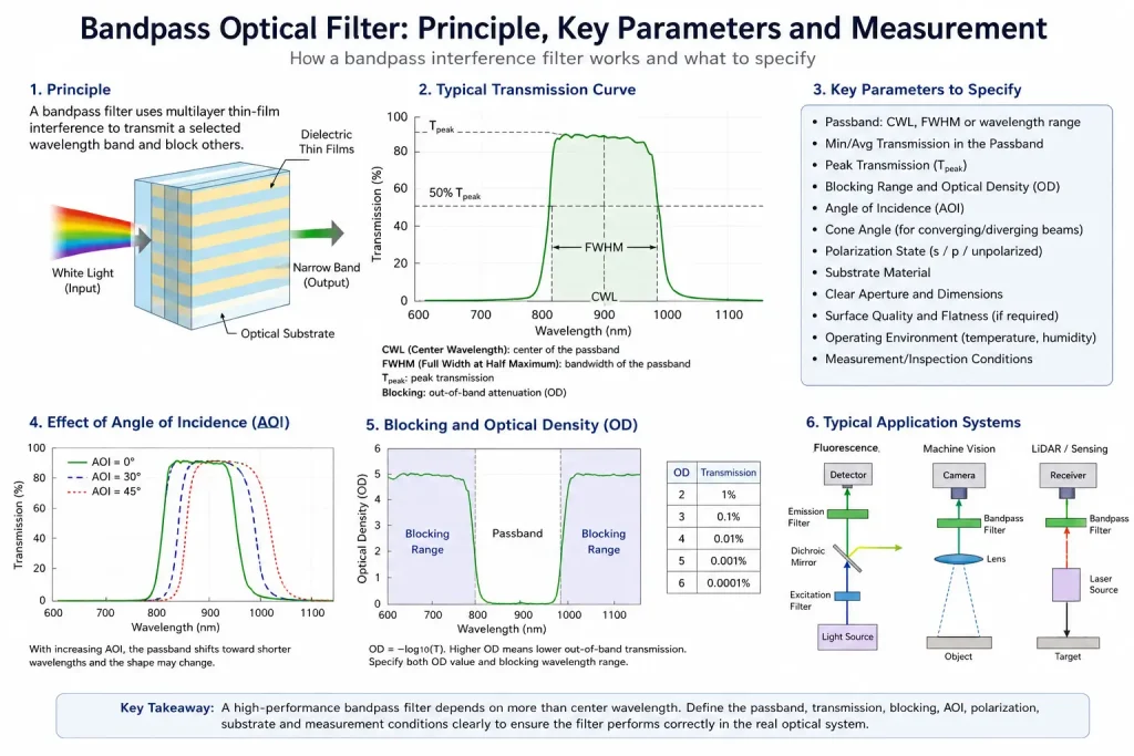
A band pass optical filter manufacturer should be evaluated by more than whether it can supply a filter at a requested center wavelength. For interference filters, center wavelength, bandwidth, passband transmission, blocking range, optical density, angle of incidence, cone angle, polarization, substrate, dimensions, and inspection conditions can all affect whether the finished component performs correctly in the optical system. The practical question is therefore not simply, “Can the manufacturer make a 532 nm or 850 nm filter?” It is whether the manufacturer can translate the real source, detector, optical geometry, and environmental requirements into a measurable filter specification and verify the finished parts against it.
What Should a Bandpass Filter Manufacturer Actually Be Able to Define?
A technically suitable manufacturer should be able to move from an application requirement to a controlled optical specification.
A bandpass filter transmits a selected spectral region while attenuating wavelengths outside that region. In thin-film interference designs, wavelength selectivity is created by multiple optical layers whose refractive indices and thicknesses are chosen so that interference favors transmission in the required band and suppresses other wavelengths. Different bandpass architectures can be used, so two filters with similar headline center wavelengths do not necessarily have identical spectral shape or angular behavior.
For many engineering projects, a useful manufacturer discussion begins with:
- required transmission wavelength range;
- center wavelength where relevant;
- FWHM or another bandwidth definition;
- minimum or average passband transmission;
- blocking wavelength range;
- required optical density;
- operating angle of incidence;
- converging or diverging beam conditions;
- polarization state;
- substrate material;
- clear aperture and mechanical dimensions;
- surface and wavefront requirements where applicable;
- operating temperature and environment;
- inspection and acceptance conditions.
This is why a drawing that specifies only “850 nm bandpass filter” is usually insufficient for a tightly controlled optical system.
Bandpass Filter, Narrow Bandpass Filter, and Interference Filter
The terminology should be clarified before a specification is released.
Bandpass filters transmit a defined band while rejecting wavelengths on both sides of that band. A narrow bandpass filter is simply a bandpass filter with a relatively narrow transmission region, but there is no single universal bandwidth threshold that separates every “narrowband” design from every broader bandpass design.
“Interference filter” describes the wavelength-selection mechanism rather than the transmitted spectral shape. An interference coating can be designed for bandpass, longpass, shortpass, notch, dichroic, or other spectral functions.
For manufacturer evaluation, the practical requirement is therefore more important than the name alone. Engineers should specify the spectral region that must pass and the region that must be attenuated instead of assuming that terms such as “narrowband” automatically define the required performance.
1. Start With the Actual Passband, Not Only the Center Wavelength
Center wavelength, or CWL, is useful, but it does not completely describe a bandpass filter.
For a conventional approximately symmetric bandpass response, CWL identifies the central region of the transmission band. FWHM—full width at half maximum—describes the wavelength separation between the two points where transmission reaches half of the applicable peak level.
A hypothetical specification might be:
- CWL: 850 nm
- FWHM: 20 nm
That information describes the approximate location and width of the band, but it does not by itself establish:
- minimum transmission across the required signal range;
- edge steepness;
- ripple within the passband;
- blocking outside the passband;
- angular shift;
- polarization behavior;
- usable clear aperture.
In many real systems, it is more useful to define a required transmission window directly—for example, a minimum transmission across a specified wavelength interval—along with separate blocking intervals. This makes acceptance less dependent on a single headline CWL or FWHM value.
2. Define Passband Transmission Correctly
“High transmission” is not a complete specification.
A manufacturer and customer should agree on whether the requirement refers to:
- peak transmission;
- minimum transmission;
- average transmission;
- transmission at one wavelength;
- or transmission across the entire specified passband.
These values are not interchangeable.
A filter could have a high peak transmission while dropping considerably near the edges of the required signal band. If the optical source itself has a finite spectral width, specifying only transmission at one nominal wavelength may therefore be inadequate.
The transmission requirement should be matched to the source spectrum and detector response rather than selected as an isolated filter parameter.
3. Specify Both Blocking Range and Optical Density
Out-of-band performance requires two pieces of information: how much attenuation is required and across which wavelengths it is required.
Optical density is related to fractional transmission by:
[
OD=-\log_{10}(T)
]
where (T) is transmission expressed as a fraction rather than a percentage.
For example, as a mathematical illustration:
| Optical Density | Fractional Transmission | Percentage Transmission |
|---|---|---|
| OD 2 | (10^{-2}) | 1% |
| OD 3 | (10^{-3}) | 0.1% |
| OD 4 | (10^{-4}) | 0.01% |
| OD 5 | (10^{-5}) | 0.001% |
These values explain attenuation only. They do not define the wavelengths over which that attenuation must be maintained.
A specification such as “OD4 blocking” is therefore incomplete without a blocking wavelength interval.
The required interval should be based on actual unwanted radiation, the detector’s sensitivity range, other optical components, and the system measurement problem. Extremely broad or deep blocking should not be requested automatically when the system does not need it.
4. Angle of Incidence Must Be Defined Before the Filter Is Designed
Angle of incidence is one of the most important variables for an interference bandpass filter.
When many thin-film interference filters are tilted away from their design angle, their spectral features shift toward shorter wavelengths. The passband shape can also change. The magnitude of the shift depends on filter design, wavelength, effective refractive index, and optical geometry.
This means a spectral curve measured at approximately normal incidence cannot automatically be treated as the performance at 30°, 45°, or another operating angle.
For a simplified interference-filter model, angular shift can be expressed approximately as:
[
\lambda_{\theta}
\lambda_{0}
\sqrt{
1-
\left(
\frac{n_0}{n_{\mathrm{eff}}}
\sin\theta
\right)^2
}
]
where the effective refractive index is design-dependent. The equation can help explain the trend, but it should not replace the actual coating model or measured data for the finished design.
A manufacturer should therefore know the intended AOI before finalizing the coating specification.
5. Cone Angle Can Matter Even When the Nominal AOI Is Zero
Not every filter operates in a perfectly collimated beam.
In imaging systems, fluorescence instruments, compact sensors, and other optical assemblies, a filter may receive light over a distribution of incident angles. A converging or diverging beam can therefore expose different portions of the beam to different effective AOIs.
For sufficiently angle-sensitive filters, this can broaden or reshape the effective spectral response rather than simply shift the entire passband by one fixed amount. Narrower filters generally require more careful consideration of this effect.
When relevant, engineers should provide:
- nominal AOI;
- cone half-angle;
- system F-number or numerical aperture information;
- filter position relative to the focusing optics.
The manufacturer can then evaluate the filter under conditions closer to its real use.
6. Polarization Becomes Increasingly Important at Oblique Incidence
At normal or near-normal incidence, polarization differences may be relatively small for many designs. At larger angles, however, s- and p-polarized light interact differently with the interfaces in the coating.
This can produce polarization-dependent spectral shifts, different transmission levels, or different edge locations.
Accordingly, an application operating at a significant AOI should state whether the incident light is:
- unpolarized;
- randomly polarized;
- linearly polarized;
- predominantly s-polarized;
- predominantly p-polarized.
A filter intended for a polarized laser path should not automatically be specified in the same way as a filter used with an unpolarized LED source.
7. Substrate Choice Is Part of the Optical Design
The coating is not the entire component.
The substrate provides the physical support for the thin-film system and can also affect transmission, wavefront quality, environmental behavior, mechanical strength, and manufacturability.
The appropriate substrate depends on factors such as:
- operating wavelength;
- required transmission range;
- diameter or rectangular dimensions;
- thickness;
- thermal environment;
- surface quality;
- flatness;
- mechanical mounting;
- coating process requirements.
Importantly, the transmission range of a bare substrate should not be confused with the measured performance of the completed coated filter. The finished spectral response depends on both the substrate and the coating system.
8. Mechanical Specifications Should Match the Optical Assembly
A technically correct spectral coating can still be difficult to integrate if the mechanical specification is incomplete.
Depending on the system, useful dimensions may include:
- outside diameter or length and width;
- thickness and thickness tolerance;
- clear aperture;
- chamfer or edge treatment;
- mounted or unmounted configuration;
- coating orientation;
- allowable cosmetic region;
- dimensional tolerances.
For filters positioned in imaging paths, surface flatness, transmitted wavefront error, wedge, or parallelism may also become relevant.
These requirements should be applied when the system needs them—not simply copied from a generic optical-component drawing.
9. Ask How Spectral Performance Is Measured
A spectral curve without measurement conditions can be misleading.
When comparing a bandpass interference filter manufacturer, engineers should determine whether reported data clearly identifies relevant conditions such as:
- wavelength range;
- measurement resolution;
- angle of incidence;
- polarization where relevant;
- transmission or OD scale;
- measured sample or theoretical design curve;
- clear-aperture measurement location;
- acceptance limits.
Commercial bandpass filter specifications commonly state AOI together with transmission, CWL, bandwidth, and blocking parameters, illustrating why spectral results need defined measurement conditions rather than an isolated curve.
For deep blocking, measurement capability also matters because verifying very low transmission is more demanding than measuring a high-transmission passband.
The procurement question should therefore be:
Can the required performance be measured with adequate range and resolution?
—not merely:
Does the supplier provide a spectrum plot?
10. Evaluate Manufacturing Capability Through the Specification
A manufacturer should be evaluated against the filter that must actually be produced.
A useful technical review can examine whether the supplier can address the following areas:
| Evaluation Area | What to Confirm |
|---|---|
| Spectral definition | Transmission band, CWL/FWHM where applicable, blocking range and OD |
| System geometry | AOI, cone angle and beam configuration |
| Polarization | Required state at the operating AOI |
| Substrate | Material, dimensions, thickness and optical requirements |
| Coating | Spectral function appropriate for the application |
| Metrology | Ability to verify the agreed wavelength and blocking requirements |
| Mechanical inspection | Size, clear aperture and drawing tolerances |
| Sampling | How prototypes or production samples will be evaluated |
| Revision control | Which drawing and spectral specification define acceptance |
| Batch acceptance | Agreed inspection criteria for production quantities |
A long list of generic capabilities is less useful than evidence that the manufacturer understands which characteristics determine the performance of the specified component.
11. How Should You Compare Two Bandpass Filter Suppliers?
Compare them using the same specification and the same measurement conditions.
One supplier quoting a higher peak transmission cannot automatically be considered better if the other supplier provides stronger required blocking, better passband uniformity, a more appropriate AOI design, or more clearly defined acceptance criteria.
Likewise, comparing OD values is meaningless if the blocking intervals differ.
A useful supplier comparison should normalize:
- transmission wavelength range;
- minimum or average transmission requirement;
- CWL/FWHM if required;
- blocking interval;
- OD requirement;
- AOI;
- cone angle;
- polarization;
- substrate and dimensions;
- inspection conditions.
Only then are the quoted optical performances technically comparable.
12. Evaluating a Bandpass Filter Manufacturer in China
When evaluating a bandpass filter manufacturer in China, use the same optical and manufacturing criteria that would apply to a supplier in any other country.
Geographic location alone does not establish whether a manufacturer can satisfy a wavelength-selective optical requirement.
Instead, verify whether the technical discussion addresses:
- the complete spectral requirement rather than one wavelength;
- actual operating AOI;
- source and detector characteristics;
- substrate and dimensions;
- blocking requirements;
- measurement conditions;
- prototype verification;
- documented acceptance criteria.
For international projects, drawing revision, units, tolerances, file versions, sample identification, and inspection documentation should also be kept unambiguous.
13. Prototype Validation Should Come Before Production Approval
For a custom filter, a representative sample should ideally be evaluated under conditions that resemble the final system before the specification is frozen for production.
A practical sequence is:
System requirement → optical specification → coating/component design → sample → spectral verification → system validation → production acceptance criteria
GIAI Photonics currently describes custom optical projects as beginning from drawings, specifications, or samples and progressing through requirement review, fabrication/coating, inspection, prototype validation, and production stages.
During sample validation, engineers should check more than whether the filter “looks correct.” Depending on the application, evaluation may include:
- measured spectral transmission;
- out-of-band blocking;
- performance at the operating AOI;
- polarization behavior;
- mechanical fit;
- clear aperture;
- image or signal performance inside the complete system.
The final system result still depends on the light source, detector, lenses, electronics, calibration, mechanics, and operating environment. A bandpass filter can contribute to wavelength selection and unwanted-background suppression, but it does not independently determine the performance of the complete instrument.
14. Application Requirements Change the Filter Specification
The same nominal wavelength can lead to different filter designs in different systems.
Machine Vision and Imaging
In machine vision, optical filters may be used to isolate illumination wavelengths or suppress part of the ambient spectrum reaching the detector.
Relevant considerations can include passband width, source spectrum, camera sensitivity, lens cone angle, clear aperture, and imaging quality.
Fluorescence Detection
Excitation and emission channels often require controlled spectral separation.
The filter needs to be evaluated together with the excitation source, fluorophore spectra, dichroic element, detector response, and optical geometry. Spectral modeling of fluorescence systems likewise treats the source, filters, fluorophore spectra, and detector response as parts of one combined system rather than evaluating a filter in isolation.
LiDAR and Optical Sensing
A bandpass filter may help limit the amount of out-of-band background reaching the receiver while transmitting the intended source wavelength.
The appropriate bandwidth and blocking depend on the laser spectrum, receiver sensitivity, AOI distribution, temperature, optical design, and ambient environment.
Spectroscopy and Gas Sensing
These systems may require relatively precise wavelength discrimination.
For narrower spectral bands, wavelength tolerance, filter temperature behavior, angular distribution, and detector response may become increasingly important.
No single generic bandpass specification is optimal for every application.
What Information Should Be Sent to a Manufacturer?
A technically efficient request should describe both the optical component and the system conditions around it.
Where available, provide:
- application;
- target wavelength or spectral feature;
- source spectrum;
- detector response range;
- required transmission band;
- minimum or average transmission;
- blocking wavelengths;
- required OD;
- nominal AOI;
- cone angle;
- polarization;
- substrate preference;
- dimensions and thickness;
- clear aperture;
- surface or wavefront requirements if applicable;
- operating temperature and environment;
- drawing or reference sample;
- expected quantity;
- inspection requirements.
Providing these inputs reduces the risk of optimizing one isolated parameter while overlooking a system-level constraint.
Conclusion
Choosing a band pass optical filter manufacturer is fundamentally a specification and verification problem.
CWL and FWHM are useful, but they are only part of the filter definition. A robust engineering specification should also consider passband transmission, blocking wavelength range, optical density, AOI, beam cone, polarization, substrate, mechanical dimensions, and measurement conditions.
The most useful manufacturer is therefore not simply the one offering the highest transmission number or deepest advertised OD. It is the one whose proposed filter can be evaluated against clearly defined operating conditions and acceptance criteria.
Engineers working on nonstandard wavelength, bandwidth, blocking, AOI, substrate, dimensions, or system-integration requirements may provide drawings, samples, source and detector information, tolerances, operating conditions, and inspection requirements to GIAI Photonics for further component evaluation. GIAI Photonics’ current manufacturing information describes custom optical projects based on drawings, specifications, and samples, with fabrication, coating, and inspection incorporated into the project workflow.
FAQ
What specifications should I send to a bandpass filter manufacturer?
At minimum, provide the required transmission wavelength range, passband transmission, blocking wavelength range, OD, operating AOI, dimensions, and intended application. For more demanding systems, also provide source spectrum, detector response, cone angle, polarization, substrate requirements, environmental conditions, and inspection criteria. CWL and FWHM alone may not completely define the performance needed in the final optical system.
Is a narrow bandpass filter always better than a broad bandpass filter?
No. A narrower passband provides greater spectral selectivity, but it can also make wavelength tolerance, AOI, cone angle, temperature, and source-spectrum matching more important. The appropriate bandwidth depends on how much of the wanted signal must pass and which unwanted wavelengths must be rejected. Narrow bandwidth should be selected because the system requires it, not because a smaller FWHM is automatically superior.
Is OD5 blocking always better than OD4?
Not necessarily. OD5 corresponds to lower transmitted out-of-band power than OD4, but deeper blocking only provides useful system benefit when it covers wavelengths that can meaningfully interfere with the detector or measurement. Optical density must always be specified together with its blocking wavelength range. Requiring unnecessarily deep or broad blocking can also make a filter specification more difficult than the application requires.
Can a filter specified at 0° AOI be used at 45°?
The 0° spectral specification should not be assumed to remain unchanged at 45°. Interference-filter spectral features generally move toward shorter wavelengths as incidence angle increases, and oblique incidence can also introduce polarization-dependent changes. A filter intended for 45° operation should therefore be designed or evaluated for that actual geometry.
What is the best way to compare bandpass filter manufacturers?
Give each manufacturer the same wavelength, transmission, blocking, OD, AOI, polarization, substrate, dimensional, and inspection requirements. Then compare responses under equivalent conditions. Peak transmission or OD values should not be compared independently when the wavelength ranges or measurement conditions differ. Prototype data and clearly documented acceptance criteria are generally more useful than comparing isolated headline specifications.
