
Technical Resources
Bandpass vs Longpass Filter for Machine Vision
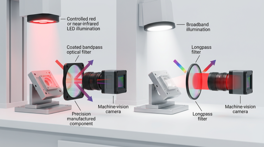
Choosing a bandpass vs longpass filter for machine vision is fundamentally a question of which wavelengths the camera should receive—and which wavelengths must be rejected. A bandpass filter transmits a defined spectral interval while attenuating wavelengths on both sides. A longpass filter blocks shorter wavelengths and transmits wavelengths above its cut-on region.
Neither architecture is universally better. A bandpass filter is usually more appropriate when a machine vision system uses wavelength-specific illumination and needs strong rejection of broadband ambient light. A longpass filter is useful when the required image information extends across a broad red or near-infrared region and rejecting shorter wavelengths is more important than defining an upper spectral boundary.
What Is the Optical Difference Between a Bandpass and Longpass Filter?
Bandpass filter
A bandpass filter has a transmission window bounded by a lower and an upper spectral edge. Light inside that band is transmitted according to the filter’s passband transmission, while wavelengths outside the band are attenuated.
For an interference bandpass filter, engineers commonly specify parameters such as center wavelength (CWL), full width at half maximum (FWHM), minimum or average in-band transmission, blocking wavelength range and optical density.
For example, a filter centered on an NIR illumination wavelength can transmit the camera signal around that wavelength while suppressing much of the visible spectrum as well as unwanted longer-wavelength radiation.
Longpass filter
A longpass filter uses a spectral transition rather than a bounded passband. Below the cut-on region, transmission is low; above the transition, transmission rises and remains relatively high over the specified pass region.
The relevant specification is therefore normally a cut-on wavelength or transition region, not a center wavelength and FWHM. A longpass filter designed for NIR machine vision might suppress visible wavelengths while allowing a broad portion of the near-infrared spectrum to reach the sensor.
The terms describe spectral function rather than the physical rejection mechanism. Depending on the design, unwanted radiation may be primarily reflected, absorbed, or controlled through a combination of substrate and coating behavior. Transmission, reflection and absorption should therefore not be treated as interchangeable quantities.
Bandpass vs Longpass Filter for Machine Vision: Direct Comparison
| Selection Factor | Bandpass Filter | Longpass Filter |
|---|---|---|
| Spectral function | Transmits a defined wavelength band and rejects wavelengths below and above it | Blocks shorter wavelengths and transmits wavelengths above the cut-on region |
| Typical machine vision use | Isolating controlled LED, laser or wavelength-specific illumination | Broad red/NIR imaging where visible or shorter wavelengths should be suppressed |
| Ambient-light rejection | Usually stronger when useful signal is confined to a narrow spectral region | Rejects short-wave ambient components but may still transmit unwanted longer wavelengths |
| Main wavelength specifications | CWL, FWHM, passband transmission and blocking range | Cut-on wavelength, transition slope, passband transmission and blocking range |
| Signal throughput | Restricted to the designed passband | Can collect a broader range of useful long-wavelength signal |
| Spectral selectivity | High when a relatively narrow passband is specified | Lower because no upper spectral boundary is created by the longpass function alone |
| Common integration concern | Passband alignment with source spectrum, AOI and detector response | Unwanted NIR transmission, detector response and cut-on behavior |
When a Bandpass Filter Is Usually the Better Choice
Machine vision often becomes more stable when illumination and detection are treated as one spectral system rather than as separate components. If an inspection station illuminates a target with a relatively narrow LED spectrum, the camera does not necessarily need to collect the rest of the available spectrum.
A bandpass filter can transmit the illumination-related signal while attenuating wavelengths that contribute primarily to background. This is especially useful where sunlight, ceiling lighting, neighboring inspection stations or other uncontrolled sources vary during operation.
Typical examples include monochrome machine vision using red or NIR LEDs, fluorescence-based inspection, wavelength-specific feature enhancement, barcode or mark detection, and optical sensing where a defined illumination band carries most of the useful information.
However, narrower is not automatically better. If the passband becomes too narrow, source spectral width, LED temperature shift, coating tolerance and incidence-angle effects can reduce useful transmission. The appropriate bandwidth should accommodate the actual source spectrum and optical geometry rather than simply minimize FWHM.
When a Longpass Filter Is More Appropriate
A longpass filter becomes attractive when the inspection signal is not confined to one narrow wavelength band. Instead, the system may benefit from collecting a relatively broad red or NIR spectrum while suppressing visible blue, green or other shorter-wavelength components.
One common case is reflected-light NIR inspection where material contrast remains useful across a relatively wide spectral region. If restricting the camera to a narrow wavelength window would unnecessarily discard signal, a longpass architecture can provide higher spectral throughput.
A longpass filter may also be useful when the engineering objective is simply to separate a longer-wavelength region from shorter-wavelength illumination. The exact result still depends on the source spectrum, object reflectance or emission spectrum, detector sensitivity and any other spectral elements in the camera.
Ambient Light Rejection Is a System-Level Question
It is tempting to conclude that a bandpass filter always provides better image contrast because it blocks more wavelengths. That conclusion is incomplete.
The camera signal depends on the spectral product of several variables: illumination output, target reflectance or emission, filter transmission, lens transmission and detector responsivity. Background light follows a similar path. A useful filter changes the balance between desired signal and unwanted background; it does not create information that was absent from the optical signal.
If useful target contrast exists across a broad NIR region, narrowing the spectrum too aggressively may remove useful photons along with ambient light. Conversely, when nearly all useful signal is concentrated around a controlled illumination wavelength, transmitting a broad spectral range can unnecessarily increase background.
This is why practical filter selection should start with measured or specified spectra rather than simply choosing a filter by its color or nominal wavelength.
CWL and FWHM Apply to Bandpass Filters, Not Longpass Filters in the Same Way
For bandpass filters, center wavelength identifies the spectral position of the passband, while FWHM describes the wavelength interval between the points where transmission is half of the relevant peak level.
These parameters should not be confused with a longpass filter’s cut-on or transition wavelength. A longpass specification describes where the filter changes from blocking to transmission rather than defining a passband midpoint.
Peak transmission and average transmission also mean different things. A high transmission value at a single wavelength does not guarantee equally high transmission across the complete useful band. For imaging applications with finite source bandwidth, the transmission curve across the source spectrum is usually more informative than a single peak number.
Optical Density and Blocking Range Matter as Much as Transmission
A filter can have excellent passband transmission and still perform poorly if unwanted wavelengths are insufficiently blocked.
Optical density expresses attenuation in the blocking region:
OD = −log10(T)
where T is fractional transmission. Therefore, OD3 corresponds to 0.1% transmission and OD4 corresponds to 0.01% transmission at the specified wavelength.
But an OD value without a wavelength range is incomplete. An engineering specification should define where that blocking level is required. The necessary range depends on the illumination spectrum, ambient environment and detector sensitivity. If the camera remains sensitive far outside the desired passband, leakage in those wavelengths may still influence the image.
For a longpass filter, engineers should similarly verify the blocked short-wave range and the useful long-wave transmission range rather than relying only on the nominal cut-on wavelength.
Why Angle of Incidence Can Change Filter Performance
Many machine vision filters use interference coatings. Their spectral response depends on the optical path through the thin-film stack, which means the measured response at one incidence angle cannot automatically be assumed to apply at another.
As the angle of incidence increases, an interference filter’s spectral features commonly shift toward shorter wavelengths. With sufficiently oblique incidence, polarization can also become relevant because s- and p-polarized components may behave differently.
This effect is particularly important in compact imaging systems with wide fields of view, fast lenses, converging beams or filter locations where rays reach the filter over a range of incidence angles. Instead of one uniform spectral shift, the filter may experience an angular distribution that broadens or modifies the effective spectral response across the field.
For that reason, the filter specification should identify the intended AOI and, when relevant, the approximate range of incident ray angles. A transmission curve measured at nominal normal incidence does not fully describe performance in a significantly different optical geometry.
Camera Spectral Response Can Change the Answer
The filter cannot be selected independently from the camera sensor and its cover-glass stack. Silicon image sensors can retain sensitivity beyond the visible spectrum, although the useful response depends on the specific sensor and camera construction.
A longpass filter intended for NIR imaging will provide little benefit if another element in the camera strongly suppresses that NIR band. Conversely, a broad longpass filter on an NIR-sensitive monochrome camera can transmit more long-wavelength background than expected if the designer evaluates only the cut-on wavelength.
Before finalizing a filter, compare at least the illumination spectrum, desired target spectrum, filter transmission and camera spectral response on the same wavelength axis.
Bandpass vs Longpass for Common Machine Vision Scenarios
| Machine Vision Scenario | Likely Starting Point | Engineering Reason |
|---|---|---|
| Controlled monochromatic LED inspection | Bandpass | Can isolate the illumination band while rejecting much of the surrounding ambient spectrum |
| Outdoor inspection under variable sunlight | Often bandpass | Spectral restriction can reduce broadband background, provided the passband remains aligned with the source |
| Broad NIR material-contrast imaging | Longpass | Preserves a wider NIR signal when an upper wavelength boundary is unnecessary |
| Fluorescence inspection | Often bandpass; sometimes longpass | Depends on emission spectrum, excitation rejection and required background suppression |
| Visible-light rejection for an NIR-sensitive camera | Longpass or dedicated NIR pass architecture | The goal may be to eliminate visible wavelengths while retaining a broad NIR region |
| Detection centered on one narrow optical signal | Bandpass | A defined passband provides stronger spectral selectivity |
How to Specify the Filter Correctly
A machine vision filter should be specified around the optical system rather than by nominal filter type alone. A useful engineering review includes the following:
- Define the useful optical signal. Identify whether the image information comes from reflection, transmission, fluorescence or another optical interaction.
- Record the illumination spectrum. Use the actual LED, laser or broadband-source spectrum rather than only its nominal wavelength.
- Review target spectral behavior. Determine where the feature being inspected produces useful contrast.
- Check detector sensitivity. Include the camera sensor and any built-in spectral filtering.
- Characterize ambient light. Determine whether visible, NIR or other background wavelengths dominate the unwanted signal.
- Define AOI and beam geometry. Include wide-field and converging-beam conditions when relevant.
- Specify blocking quantitatively. Define both optical density and the wavelength interval over which it is required.
- Verify mechanical integration. Clear aperture, thickness, mounting position and possible vignetting can affect the final system.
- Test the assembled optical path. Evaluate actual image contrast and stability rather than relying exclusively on a standalone filter curve.
Common Selection Mistakes
Choosing only from the nominal wavelength
A label such as 850 nm or 940 nm does not define the complete source spectrum, filter bandwidth or sensor response. The spectra must overlap appropriately under operating conditions.
Assuming maximum transmission describes the entire passband
Peak transmission is one point on the spectral curve. Average or minimum transmission across the useful spectrum may be more relevant for imaging throughput.
Ignoring the blocking range
OD without a specified wavelength interval does not tell the engineer whether leakage occurs where the camera remains sensitive.
Assuming normal-incidence data applies at another AOI
Interference-filter performance can move when the incidence angle changes. The actual beam geometry should be considered before locking the specification.
Using a longpass filter when long-wavelength background is significant
A longpass architecture deliberately continues transmitting beyond the cut-on region. If unwanted radiation exists at longer wavelengths, a bandpass or another spectral architecture may provide better separation.
Using an unnecessarily narrow bandpass
Very narrow filtering can improve spectral discrimination but may also increase sensitivity to source shift, coating tolerance and incidence angle while reducing usable signal. Bandwidth should follow the optical requirement rather than a general assumption that narrower is superior.
Practical Selection Rule
Start with a bandpass filter when:
- The illumination occupies a defined wavelength band.
- Ambient light exists both below and above the signal wavelength.
- Spectral selectivity is more important than maximum broadband throughput.
- The detector should primarily see the controlled illumination signal.
Start with a longpass filter when:
- The useful signal extends broadly toward longer wavelengths.
- Short-wavelength rejection is the main filtering objective.
- Broad red or NIR throughput is desirable.
- Longer-wavelength background will not compromise the measurement.
The final choice should then be checked against optical filter parameters such as transmission, blocking and AOI; the available optical filters; and, where a defined spectral window is required, the engineering considerations used for a custom bandpass interference filter. A machine-vision implementation such as a machine vision bandpass filter can also provide a useful reference for how wavelength, FWHM and blocking requirements are expressed in an application-specific component.
Conclusion
The main difference between a bandpass and longpass filter is not simply that one is “narrow” and the other is “broad.” They impose different spectral boundaries on the machine vision system.
A bandpass filter is generally the stronger starting point when a camera must isolate a defined illumination or signal band from broadband background. A longpass filter is more appropriate when useful information occupies a broad longer-wavelength region and rejecting shorter wavelengths is sufficient.
Reliable selection requires looking beyond the filter name. Source spectrum, target response, detector sensitivity, CWL or cut-on wavelength, bandwidth, blocking range, optical density, AOI, polarization where relevant, and mechanical integration all influence the result. Final performance should be verified under the actual optical geometry and illumination conditions of the machine vision system.
FAQ
What is the main difference between a bandpass and longpass filter in machine vision?
A bandpass filter transmits a defined wavelength interval while suppressing wavelengths on both sides, whereas a longpass filter blocks shorter wavelengths and transmits wavelengths above its cut-on region. For machine vision, bandpass filters are often selected when illumination is concentrated around a controlled wavelength and ambient-light rejection is important. Longpass filters are useful when the system benefits from collecting a broad red or NIR spectrum rather than isolating a narrow band.
Is a bandpass filter always better for reducing ambient light?
No. A bandpass filter can provide stronger spectral restriction because it blocks wavelengths on both sides of the transmitted band, but the correct choice depends on where useful signal and background actually occur. If useful target information extends across a broad NIR range, narrowing the passband may reduce signal unnecessarily. Filter selection should be based on the illumination spectrum, object response, ambient spectrum and detector sensitivity rather than filter type alone.
How should FWHM be selected for a machine vision bandpass filter?
FWHM should be wide enough to transmit the useful source spectrum under expected wavelength tolerances and operating conditions, but narrow enough to reject unwanted background effectively. Engineers should consider LED or source bandwidth, temperature-dependent source shift, filter manufacturing tolerance, incidence-angle effects and sensor response. Selecting the narrowest possible FWHM without considering these factors can reduce useful signal and make the imaging system less tolerant of optical or environmental variation.
Does angle of incidence affect both bandpass and longpass filters?
It can, particularly when the spectral function is produced by an interference coating. Increasing angle of incidence commonly shifts interference-filter spectral features toward shorter wavelengths, and a distribution of ray angles can modify the effective edge or passband. The magnitude depends on the filter design and optical geometry. Therefore, transmission data measured at 0° should not automatically be applied to a filter operating at a substantially different AOI.
What specifications should be provided when selecting a machine vision filter?
Provide the illumination spectrum, desired transmitted wavelength range, required transmission, blocking wavelength range, optical density, angle of incidence, beam geometry, sensor spectral response, clear aperture, dimensions and operating environment. For a bandpass design, CWL and FWHM are normally important. For a longpass design, define the cut-on or transition region and required longer-wavelength transmission. Where possible, evaluate the complete spectral curve rather than relying on one nominal wavelength value.
