
Technical Resources
F-Theta Lens Spot Size vs Beam Diameter
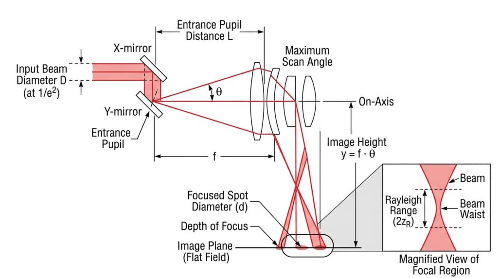
In an f-theta scanning system, spot size and input beam diameter are inversely related: double the collimated beam diameter at the lens, and the focused spot diameter halves. That single relationship is the reason a beam expander sits between almost every laser and every galvanometer scanner. Understanding f-theta lens spot size vs beam diameter matters because the same expansion that shrinks your spot also shortens your depth of focus by the square, and can push the beam past the lens aperture at large scan angles.
The rest of this article covers the governing equations, the constants that vendors actually use, what changes across the scan field, and the specification mistakes that show up as faded marks in the corner of a workpiece.
The governing relationship
For a collimated Gaussian beam focused by a lens, the diameter of the focused spot is:
d = C · λ · f / D
Where:
- d = focused spot diameter at the image plane, measured at 1/e² of peak intensity
- λ = wavelength
- f = effective focal length (EFL) of the f-theta lens
- D = collimated input beam diameter at the lens entrance pupil, at 1/e²
- C = a constant set by how the beam fills the aperture
Note the units. If λ is in nanometers, f in millimeters, and D in millimeters, the result comes out in micrometers directly.
The relationship is inverse and linear. Spot size scales with focal length, and inversely with input beam diameter. Nothing about the lens design changes that; a well-corrected f-theta lens simply gets close to the diffraction limit that this equation describes, while a poorly corrected one falls short of it.
Why the constant is not always 1.27
For an ideal Gaussian beam that passes through an aperture much larger than itself, C = 4/π ≈ 1.27. This is the textbook diffraction limit.
Most f-theta lens vendors, including Thorlabs and LINOS, publish spot size calculations using C = 1.83, which applies when the entrance beam is truncated at its 1/e² diameter by the aperture. Truncation clips the wings of the Gaussian, and a clipped aperture function produces a broader central lobe plus low-level side rings.
This is not a rounding difference. At the same beam diameter, the two constants differ by 44 percent. If you compare a vendor’s published spot size against your own calculation and find a mismatch, check which constant each of you used before you suspect the lens.
The practical guidance: if your beam is comfortably smaller than the clear aperture, use 1.27 as an optimistic floor. If the beam fills the specified maximum input diameter, use 1.83. Between those cases the constant varies continuously with the truncation ratio, and the honest answer is that it is design dependent.
Where beam quality enters
Real beams are not ideal. The beam quality factor M², defined so that M² = 1 for a perfect Gaussian, multiplies the spot diameter directly:
d = C · λ · f · M² / D
A single-mode fiber laser typically delivers M² below about 1.2. Multimode fiber lasers, diode-pumped solid-state lasers at high average power, and direct diode sources can run substantially higher. Using an M² = 1 calculation to specify a system running a multimode source is one of the most common ways a marking system ends up with a spot two or three times wider than the design intent.
F-theta lens spot size vs beam diameter: a worked example
The table below uses λ = 1064 nm, EFL = 160 mm, and M² = 1. Depth of focus is given as the Rayleigh range z_R = π·w₀²/(λ·M²), where w₀ is the spot radius, using the untruncated spot values.
| Input beam Ø (1/e²) | Spot Ø, C = 1.27 | Spot Ø, C = 1.83 | Depth of focus (±z_R) |
|---|---|---|---|
| 5 mm | 43 µm | 62 µm | ±1.38 mm |
| 8 mm | 27 µm | 39 µm | ±0.54 mm |
| 10 mm | 22 µm | 31 µm | ±0.34 mm |
| 14 mm | 15 µm | 22 µm | ±0.18 mm |
| 20 mm | 11 µm | 16 µm | ±0.09 mm |
Two things stand out. Going from 5 mm to 20 mm of input beam shrinks the spot by a factor of four, exactly as the inverse relationship predicts. Over the same range, depth of focus collapses by a factor of sixteen.
These are theoretical, diffraction-limited numbers. Measured spots run larger because of residual aberration, coating and substrate wavefront error, beam pointing, and thermal effects. Treat the calculation as a lower bound, not a specification.
Depth of focus is the price you pay
Because depth of focus scales with the square of the spot diameter, it falls with the square of the input beam diameter:
z_R = 4·λ·M²·f² / (π·D²)
This is the trade-off that decides most system architectures. A 10 µm spot on a part with 0.3 mm of surface variation will produce visibly inconsistent results, because the surface wanders outside the focal volume. A 40 µm spot on the same part is forgiving.
Before you specify a spot size, add up the axial error budget: workpiece flatness, fixturing repeatability, part-to-part thickness tolerance, field curvature residual of the lens, and thermal focus shift. If that total exceeds the depth of focus your spot size implies, you either accept the variation, add a dynamic focus module, or use a larger spot.
The aperture limits how far you can expand
You cannot keep expanding the beam indefinitely, and the limit is usually not the physical diameter of the front element.
An f-theta lens is specified with an entrance pupil distance, sometimes called the scanner mounting distance. The lens is corrected on the assumption that the beam pivots at that plane. In a two-mirror galvanometer scanner there is no single stationary pivot point, so the design pupil sits between the two mirrors, and the mirror separation should be kept as small as the mechanics allow.
At a scan angle θ, the beam center is displaced laterally at the lens entrance by approximately L·tan θ, where L is the distance from the pupil to the first element. Consider an EFL of 160 mm covering a 110 mm square field. The corner sits at a half-diagonal of 77.8 mm, so θ = 77.8/160 = 0.486 rad, or 27.9 degrees. With L = 25 mm, the beam center walks about 13 mm off axis. A 10 mm beam then reaches 18 mm from the axis, requiring roughly 36 mm of clear aperture at that field point.
This is why lens datasheets specify maximum input beam diameter as a smaller number than the clear aperture. The difference is reserved for beam walk. Exceed it, and the beam clips at the field corners.
The failure mode is distinctive: the center of the field marks correctly, power drops toward the corners, and the corner spot is broader and asymmetric with visible side structure. Engineers often chase this as a galvo calibration problem or a laser problem. It is neither. It is vignetting caused by a beam that is too large, a scanner mounted at the wrong distance, or both.
Spot size is not constant across the field
Even without vignetting, the corner spot in a non-telecentric f-theta system is larger than the center spot for three reasons.
First, the output scan angle is nonzero at the field edge, so the beam meets the workpiece at an angle. The footprint stretches along the scan direction by roughly 1/cos θ. At 28 degrees that is about 13 percent of elongation.
Second, residual field curvature means the beam waist does not land exactly on the flat image plane everywhere.
Third, off-axis aberrations, primarily astigmatism and coma, grow with field angle.
Telecentric f-theta lenses solve the first two by keeping the output beam normal to the image plane, which gives a more uniform spot and eliminates the positional error caused by part height variation. The cost is severe: the front element must be at least as large as the scan field, so telecentric designs are practical only for small fields and are far more expensive per unit area.
Datasheet parameters that set spot size
| Parameter | What it tells you | Effect on spot |
|---|---|---|
| Design wavelength | The λ the lens is corrected and coated for | Enters directly; also determines whether the lens works at all |
| Effective focal length (EFL) | Focal length used in y = f·θ | Spot scales linearly with EFL |
| Max input beam diameter | Largest beam that clears the aperture across the full field | Sets the smallest achievable spot |
| Entrance pupil distance | Where the scanner pivot must sit | Wrong value causes corner vignetting |
| Scan field size | Usable square or diagonal field | Larger field forces larger max scan angle, reducing usable beam diameter |
| f-theta distortion | Deviation from y = f·θ, in percent of field | Affects spot position, not spot size |
| Back working distance | Housing face to focal plane | Sets mechanical clearance and focus setting |
| Surface figure | Wavefront error per surface, in λ P-V (peak to valley) | Degrades spot below the diffraction limit if loose |
| Surface quality | Scratch-dig per MIL-PRF-13830B, or ISO 10110 notation | Scatter and, at high power, damage initiation sites |
| AR coating and LIDT | Anti-reflection coating band, laser-induced damage threshold | Transmission loss and survival at power |
For 1064 nm and ultraviolet systems, fused silica elements are common because their low absorption reduces thermal focus shift. Scan lens vendors commonly flag thermal shift as a practical concern above roughly 50 W of average power at 1064 nm in conventional optical glasses, though the exact onset depends on the design, duty cycle, and how clean the optics are. Carbon dioxide laser systems at 9.3 or 10.6 µm use zinc selenide, which has its own thermal lensing behavior. GIAI Photonics supplies f-theta lenses along with the beam expanders, protective windows, and custom coatings that sit around them in a scanning head.
Surface figure on f-theta elements is typically specified in the λ/4 to λ/2 P-V range at 633 nm, and surface quality commonly at 40-20 or 60-40 scratch-dig, but both vary by supplier and by whether the lens is aimed at marking or at micromachining.
Common specification mistakes
Quoting a spot size without stating the beam diameter. A spot size specification is meaningless on its own. It always assumes a wavelength, a focal length, an input beam diameter, a truncation condition, and an M². Ask for all five.
Measuring beam diameter at the laser output instead of at the lens. The number that goes into the equation is the diameter at the entrance pupil, after the beam expander and after whatever propagation distance exists. Beams diverge. A 10 mm beam at the expander output may be 10.4 mm by the time it reaches the lens.
Mixing FWHM and 1/e² diameters. For a Gaussian, the full width at half maximum (FWHM) diameter equals 0.589 times the 1/e² diameter. Confusing them introduces a factor of 1.7 in either direction. Many laser datasheets quote FWHM; almost all lens datasheets quote 1/e².
Chasing the smallest possible spot. Expanding to fill the aperture gives the smallest spot and the shortest depth of focus, the tightest focus-height tolerance, and the highest sensitivity to beam pointing. In production marking, a slightly larger spot is often the more repeatable choice.
Ignoring the entrance pupil distance during mechanical design. Once the scanner mounting bracket is machined, this becomes expensive to fix.
How to choose an input beam diameter
- Start from the process requirement, not the spot size. Determine the minimum feature width, kerf, or line width you need.
- Set a target spot diameter, allowing margin above the theoretical value for aberration and beam quality.
- Compute the required input beam diameter from D = C·λ·f·M²/d, using C = 1.83 if the beam will fill the aperture.
- Check that D is below the lens maximum input beam diameter. If not, either shorten the EFL, which also shrinks the field, or accept a larger spot.
- Compute the resulting depth of focus and compare it against your axial error budget. If the budget loses, go back to step 2.
- Select the beam expander magnification that produces D from your laser’s native output diameter, and verify the expander’s own clear aperture and damage threshold.
FAQ
Does a larger input beam give a larger focused spot? No, the opposite. A larger collimated beam converges at a steeper angle, which produces a smaller diffraction-limited waist. Spot diameter is inversely proportional to input beam diameter. The intuition that fails here comes from imaging, where object and image scale together; a focused laser beam is a diffraction problem, not an imaging one.
How do I convert an FWHM beam diameter to 1/e²? For a Gaussian profile, multiply the FWHM diameter by 1.699 to get the 1/e² diameter, or multiply the 1/e² diameter by 0.589 to get FWHM. A beam specified as 6 mm FWHM is 10.2 mm at 1/e². Always confirm which convention a datasheet uses before putting the number into a spot size calculation.
What beam expander magnification do I need to halve my spot? Exactly 2x, since spot size is inversely proportional to input beam diameter. Before committing, check two things: that the doubled beam stays within the lens maximum input beam diameter across the full scan field, and that the resulting depth of focus, which drops by a factor of four, still covers your axial error budget.
Why is the spot larger at the corners of my scan field? Three effects combine. The output beam meets the workpiece at an angle in a non-telecentric design, elongating the footprint by about 1/cos θ. Residual field curvature displaces the waist from the flat image plane. Off-axis aberrations grow with field angle. If the corner spot is also dimmer, suspect vignetting from an oversized beam or an incorrect scanner mounting distance.
Does beam quality change depth of focus? For a fixed input beam diameter, increasing M² increases both the spot diameter and the Rayleigh range in proportion. A beam with M² = 2 focuses to twice the waist of an ideal beam but stays in focus over twice the distance. That is why some processes deliberately accept a higher M² source when axial tolerance matters more than feature size.
Can I use a 1064 nm f-theta lens at 532 nm? No. The anti-reflection coating is designed for a specific band, so transmission at the wrong wavelength drops sharply and reflected power can damage upstream components. The chromatic correction and field flattening are also wavelength specific, so focal length shifts and field flatness degrades. Multi-wavelength f-theta designs exist and must be ordered as such.
Closing
Once you have settled on a target spot size, depth of focus, and field, the remaining work is matching the f-theta lens, beam expander, and protective window to your wavelength and power, which is where the GIAI Photonics optical lens range is worth a look.
