
Technical Resources
Raman Edge Filter vs Notch Filter: How to Choose
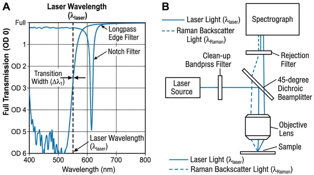
Choose a Raman edge filter when you only need Stokes signal and you want to measure as close to the laser line as physically possible. Choose a notch filter when you need Stokes and anti-Stokes in the same acquisition, or when your excitation wavelength moves enough that you need real angle-tuning range. Both types are available with optical density (OD) greater than 6 at the laser line, so the decision is almost never about blocking depth. It is about transition width, passband coverage, and tuning range.
The rest of this article covers the physics that sets those limits, the datasheet parameters that actually matter, and the specification mistakes that put full-power Rayleigh light on a detector.
Why Raman needs a rejection filter at all
Spontaneous Raman scattering is weak. Only a small fraction of incident photons, commonly quoted as roughly one in 10^6 to 10^8, scatters inelastically. Everything else comes back at the excitation wavelength as elastically scattered Rayleigh light. Without a rejection filter, that Rayleigh light saturates the detector and floods the spectrograph with stray light that appears as a sloping background across the entire spectrum.
The Raman shift is measured in wavenumbers, not nanometers:
Δν̃ (cm⁻¹) = (1/λ_L − 1/λ_s) × 10⁷, with λ in nm
For small shifts near the laser line, the conversion between a wavelength offset and a wavenumber offset is:
Δν̃ ≈ Δλ × 10⁷ / λ_L²
That second equation is the one to keep in your head, because it explains why filter specifications are quoted as a percentage of the laser wavelength. At 785 nm, a 3.9 nm offset from the laser line equals 63 cm⁻¹. At 532 nm, the same 3.9 nm equals 138 cm⁻¹. A filter grade that gives you comfortable low-wavenumber access at 785 nm gives you much less at 532 nm.
Edge filter and notch filter: what each one blocks
A longpass (LP) edge filter transmits everything above a cut-on wavelength and blocks everything below it. Placed in the collection path after the sample, it blocks the laser line and all shorter wavelengths, and transmits the Stokes-shifted Raman signal. A shortpass (SP) edge filter does the reverse and is used when you want anti-Stokes only.
A notch filter blocks a narrow band centered on the laser line and transmits on both sides. The two passbands give you Stokes and anti-Stokes simultaneously.
Both are dielectric thin-film interference coatings, typically alternating high-index and low-index oxide layers such as Ta₂O₅ and SiO₂ deposited by ion-beam or magnetron sputtering. Both reflect the rejected light rather than absorbing it, which keeps the laser damage threshold high and gives you a usable reflected beam for alignment.
The functional difference is structural. An edge filter needs one steep transition. A notch filter needs two steep transitions plus wide, flat, harmonic-free passbands on either side, which takes substantially more layers. That layer count is the root of most of the trade-offs below.
Transition width and edge steepness: the specification that decides everything
Two terms get confused constantly, and only one of them tells you how close to the laser line you can measure.
Transition width is the spectral distance from the laser line, where the filter guarantees OD > 6, to the 50% transmission wavelength. This is the number that determines your lowest accessible Raman shift.
Edge steepness is the distance from the highest wavelength at OD 6 to the 50% transmission wavelength, regardless of where the edge sits relative to the laser. A filter can have an excellent steepness and still have a wide transition width if the edge is placed conservatively far from the laser line.
Specify transition width. Steepness alone does not guarantee low-wavenumber access.
Published guaranteed transition widths from one widely used catalog line (Semrock) give a useful sense of what is commercially available:
| Filter grade | Guaranteed transition width (% of λ_L) | Equivalent at 532 nm | Equivalent at 785 nm |
|---|---|---|---|
| Ultrasteep (Verona) | < 0.2% | < 39 cm⁻¹ | ~25 cm⁻¹ |
| RazorEdge E-grade | < 0.5% | < 90 cm⁻¹ | ~63 cm⁻¹ |
| RazorEdge U-grade | < 1.0% | < 186 cm⁻¹ | ~126 cm⁻¹ |
| EdgeBasic | < 2.5% | < 458 cm⁻¹ | ~315 cm⁻¹ |
Thin-film notch filters do not transition as close to the laser line as the steepest edge filters. If your analyte has diagnostic bands below roughly 100 cm⁻¹ and you only need Stokes, an ultrasteep edge filter is the right part. If your bands sit above 200 cm⁻¹, the transition width argument mostly disappears and other factors decide.
Raman edge filter vs notch filter: parameter comparison
| Parameter | Longpass edge filter | Thin-film notch filter | Volume Bragg grating (VBG) notch |
|---|---|---|---|
| Laser-line blocking | OD > 6 available | OD > 6 available | Typically OD 3 to 4, higher available |
| Lowest accessible shift | Set by transition width; ultrasteep grades reach tens of cm⁻¹ | Wider than the steepest edge filters | Cut-off reported near 3 to 5 cm⁻¹ |
| Anti-Stokes access | No (LP blocks it entirely) | Yes, both passbands | Yes |
| Angle tuning range | About 0 to 8°, roughly 0.3% of λ_L | About 0 to 14°, roughly 1% of λ_L | Very small; alignment tolerance near 0.1° |
| Alignment sensitivity | Low | Low to moderate | High |
| Passband width | Very wide above the edge | Wide but bounded by harmonic stopbands in some designs | Narrow rejection band, otherwise transparent |
| Out-of-band stray light rejection | Blocks all shorter wavelengths, helps background | Passes short wavelengths, needs extra clean-up | Passes nearly everything else |
| Relative cost | Lowest for a given blocking depth | Higher; more layers required | Highest per channel |
Cost ordering is typical rather than universal and varies by supplier, wavelength, and volume.
Angle of incidence, tuning, and polarization
Every dielectric interference filter blue-shifts as you tilt it:
λ(θ) = λ₀ × √(1 − (sin θ / n_eff)²)
where n_eff is the effective index of the coating stack, typically between about 1.4 and 2.2. A common estimate is the geometric mean of the lowest and highest index materials in the stack, so a SiO₂ and Ta₂O₅ design lands near 1.73.
For small angles this reduces to a form that is easier to use at the bench:
Δλ (nm) ≈ −5.0 × 10⁻⁵ × λ_L × θ² and Δν̃ (cm⁻¹) ≈ 500 × θ² / λ_L, with θ in degrees
Two consequences follow. First, you can deliberately tilt a filter to move its edge onto a slightly different laser wavelength. Edge filters are usually specified for tuning from 0 to about 8°, which buys roughly 0.3% of the laser wavelength. Notch filters tune from 0 to about 14°, roughly 1%. That larger tuning range is the second real advantage of a notch filter, and it matters when a production line has to accept lasers binned across a wavelength tolerance.
Second, tilt is not free. As the angle of incidence (AOI) increases, s-polarized and p-polarized light see different effective indices. The blocking band splits, notch depth decreases, and the notch narrows, with p-polarized light degrading faster in typical designs. Raman scattering from most samples is at least partially depolarized, so you cannot assume one polarization state. If you tune past a few degrees, verify OD for both polarizations rather than trusting the 0° curve.
When only a notch filter will do
Anti-Stokes measurement. Anti-Stokes intensity follows a Boltzmann population factor, approximately exp(−hcΔν̃ / kT). At 300 K, kT/hc is about 208 cm⁻¹, so anti-Stokes bands are weak but usable at low wavenumbers and become the basis for optical thermometry, since the Stokes to anti-Stokes ratio is temperature dependent. An LP edge filter blocks the anti-Stokes side completely.
Ultra-low-frequency Raman. Lattice modes in pharmaceutical polymorphs, shear and layer-breathing modes in layered materials, and phonon modes in semiconductors sit below 100 cm⁻¹, sometimes below 20 cm⁻¹. VBG notch filters, holographic gratings recorded in photo-thermo-refractive glass, reach cut-off frequencies reported in the 3 to 5 cm⁻¹ range and replace the triple-monochromator setups that used to be required. The cost is alignment: published angular scans show the deep rejection window can be as narrow as about 0.1°, so these parts need stable, well-controlled mounting.
Multi-wavelength systems. Multi-notch filters block several laser lines with a single part, which is why they appear in confocal and multiphoton systems that share a detection path.
What you give up
Pushing transition width down means more coating layers, tighter thickness control, and lower yield. You pay in unit cost, in passband transmission near the edge, and in sensitivity to beam geometry. A very steep edge is only steep for well-collimated light.
Notch filters buy you anti-Stokes and tuning range but pass everything outside the notch. Ambient room light, laser plasma lines, and short-wavelength fluorescence all reach the spectrograph. Notch systems therefore need a laser-line clean-up bandpass filter and more attention to baffling than edge-filter systems, where the longpass is already removing the entire short-wavelength half of the spectrum.
Thermal drift is a minor term for hard-coated filters, with published values around 2 to 5 pm/°C, but it is not zero for ultra-narrow parts in wide-temperature instruments.
Common specification mistakes
Specifying the filter against the nominal laser wavelength instead of the real one. An unstabilized Fabry-Perot laser diode can drift on the order of 0.2 to 0.3 nm/°C. Over a 20 °C ambient swing, a nominally 785 nm diode can move roughly 5 nm. An edge filter with a 0.5% transition width reaches 50% transmission near 788.9 nm, so a laser that drifts to 790 nm is now sitting in the filter’s passband. The result is full-power Rayleigh light on the detector, a saturated spectrum, and a fault that appears only in the field on hot days. Either specify a VBG-stabilized or DBR laser, where drift near 0.01 nm/°C is achievable, or specify a filter with enough blocking bandwidth to cover the full drift range.
Using a dichroic beamsplitter that is less steep than the rejection filter. In a backscatter probe with a common excitation and collection path, the 45° dichroic sets the limit. If the dichroic transition is wider than the edge filter transition, the low-wavenumber performance you paid for is gone. Specify the dichroic transition first, then match the edge filter to it.
Putting the filter in a converging beam. In an f/2 beam, the marginal ray hits the filter at about 14° from normal. Using the small-angle approximation at 785 nm, that ray sees an edge blue-shifted by roughly 7.7 nm relative to the chief ray. The measured edge is the average across the cone, so a filter with a 3 nm transition width degrades to something closer to 10 nm. Mount rejection filters in collimated space, or budget explicitly for the cone angle.
Reading OD at the wrong wavelength. OD > 6 is often guaranteed over a narrow band centered on the laser line, with lower blocking outside it. Check the blocking range and blocking depth as separate line items, and confirm they cover the laser’s amplified spontaneous emission sidebands, not just the center wavelength.
Ignoring aperture and surface specification. Clear aperture is smaller than the outside diameter, and coating uniformity degrades toward the edge of the deposition zone. Confirm that the surface specification suits the position: scratch-dig per MIL-PRF-13830B and surface figure or transmitted wavefront error per ISO 10110 matter far more for a filter in an imaging path, or for a dichroic used in reflection, than for one in a non-imaging collection leg. Suppliers such as GIAI Photonics list longpass and shortpass filters, notch filters, and dichroic filters as separate categories, and these specifications differ meaningfully between them.
How to choose
- Stokes only, need bands below 100 cm⁻¹: ultrasteep longpass edge filter, collimated mount, stabilized laser.
- Stokes only, bands above 300 cm⁻¹, cost sensitive: a basic-grade edge filter is usually sufficient.
- Need anti-Stokes, or thermometry from the Stokes to anti-Stokes ratio: thin-film notch filter.
- Need bands below 20 cm⁻¹: VBG notch filter, with the mechanical stability to hold sub-0.1° alignment.
- Production instrument with binned lasers: notch filter for its wider angle-tuning range, or an edge filter plus a tighter laser specification.
- Multiple excitation wavelengths on one detection path: multi-notch filter.
FAQ
Can I get OD 12 by stacking two OD 6 filters? Not reliably. Two filters in series improve blocking, but the achieved OD is limited by scattered light, inter-surface reflections, and the dynamic range of your own measurement. Treat stacking as a way to gain margin, not as simple arithmetic, and verify the result in the actual optical path rather than on a spectrophotometer.
Does a notch filter block anti-Stokes fluorescence too? No. A notch filter blocks only its rejection band. Fluorescence on the short-wavelength side of the laser passes straight through to the spectrograph. This is one reason 785 nm excitation with an edge filter is common for fluorescent samples: the edge filter removes that entire spectral region.
Why did my measured edge look less steep than the datasheet? Most often the beam is not collimated at the filter, or the AOI is not what you assumed. Both smear the edge. Check the cone half-angle, confirm the filter is normal to the chief ray, and verify polarization if you have tilted the part more than a few degrees.
Does filter orientation matter? Yes. Coated filters have a specified propagation direction, usually marked with an arrow on the mount ring. Reversing the part changes the coating-to-substrate order seen by the incoming light and can raise the stray-light background. For dichroics, the coated face normally points toward the source and sample.
Should the rejection filter or the clean-up filter be specified first? Specify the laser and its wavelength tolerance first, then the dichroic, then the rejection filter, then the clean-up bandpass. Every downstream part inherits the laser’s uncertainty, and the dichroic caps the achievable low-wavenumber performance in a common-path probe.
Are edge and notch filters interchangeable for a fixed-wavelength OEM instrument? Only if you never need anti-Stokes and the laser wavelength is tightly held. In that case the edge filter usually wins on cost, transition width, and stray-light rejection.
If you are sourcing parts for a Raman detection path, the relevant categories are longpass and shortpass filters, notch filters, and dichroic filters, all of which GIAI Photonics supplies as standard and custom-coated components.
