
Technical Resources
Choosing Fluorescence Filters
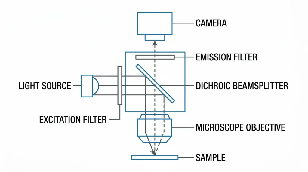
Treat the three components as one optical system. To choose excitation, emission, and dichroic filters for fluorescence, start from the fluorophore’s absorption and emission spectra, place the dichroic edge in the crossover region between them, then set the exciter and emitter passbands so their combined blocking at that crossover is deep enough to bury the leaked excitation light. Everything after that, transmission, edge steepness, flatness, and angle tolerance, is decided by how much signal you need and how dark the background has to be.
Why the three filters are a single design problem
A fluorophore absorbs over a broad band and re-emits at longer wavelengths. The separation between the absorption peak and the emission peak is the Stokes shift, and for common visible dyes it is small relative to the width of either band. The two spectra therefore overlap, and the wavelength where the normalized curves cross is the crossover point.
That crossover is where the whole design is won or lost. Push the exciter passband to longer wavelengths and you excite more molecules, but you move excitation light into the emission band. Push the emitter passband to shorter wavelengths and you collect more photons, but you collect more scattered excitation light with them.
The detected signal scales with the excitation power delivered inside the absorption band, the fluorophore’s extinction coefficient and quantum yield, and the product of the emission-path transmissions. The background from excitation leakage scales with the source power multiplied by the excitation-path and emission-path transmission at the same wavelength. Since the excitation power at the sample is many orders of magnitude larger than the fluorescence returning from it, the blocking budget dominates.
The dichroic is not a blocking filter
This trips up people building custom sets. A dichroic that reflects 98% of the excitation band still transmits about 2% of it, which is roughly optical density (OD) 1.7. That is useful, but it is not blocking. Most dichroic datasheets specify average reflection and transmission, not OD, and offer no guarantee at all outside the specified bands.
The practical rule from filter-set design practice is that the exciter and emitter together should reach OD 7 to OD 8 at the crossover, with the split between them left to the designer. For a laser-based system, the emitter must also block at the laser line specifically, and OD 6 is a common floor, with OD 8 used in total internal reflection fluorescence (TIRF) and single-molecule work. An emission filter chosen for a broadband lamp will not necessarily block a laser line that sits in a gap in its blocking range.
The datasheet parameters that actually decide performance
| Parameter | What it tells you | Typical range or convention | Consequence if wrong |
|---|---|---|---|
| Center wavelength (CWL) and full width at half maximum (FWHM) | Passband position and width | Quoted at a stated angle of incidence (AOI), usually 0° for exciters and emitters, 45° for dichroics | Misplaced band costs signal or adds crosstalk |
| Peak and average transmission | Photon throughput in band | Hard-coated filters commonly exceed 90% average, with better than 95% achievable on well-designed bands | Directly multiplies into signal |
| Blocking (OD) and blocking range | Attenuation outside the band, and over what span it is guaranteed | OD 6 is standard for fluorescence emitters; the guaranteed range matters as much as the number | Out-of-range leakage raises background |
| Transition width | Steepness, usually as a percentage of the edge wavelength | Steep edge filters reach transition widths well under 1% of the edge wavelength | Shallow edges force wider gaps and lose signal |
| Effective index (n_eff) | Governs blue shift with angle | Roughly 1.6 to 2.1 depending on coating materials and polarization | Determines angle tolerance |
| Temperature coefficient | Thermal drift of the passband | Hard-coated filters typically a few pm/°C; older soft-coated designs an order of magnitude higher | Matters for narrowband and for hot enclosures |
| Surface flatness, peak-to-valley (P-V) | Substrate shape after coating | Widefield epi dichroics often around 10 waves per inch; laser and TIRF grades far tighter | Sets reflected wavefront error (RWE) and focus shift |
| Transmitted wavefront error (TWE) | Distortion of the imaging path | Roughly 1 wave per inch for widefield, tighter for confocal | Blurs the image |
| Wedge angle | Parallelism of the two faces | 1 arcminute or better for widefield dichroics | Causes image shift when filters are swapped |
| Surface quality (scratch-dig) | Cosmetic defects per MIL-PRF-13830B, or ISO 10110 equivalent | 40/40 is common for dichroics, tighter for pupil-plane optics | Scatter adds background |
| Substrate and coating type | Autofluorescence and durability | Fused silica preferred for dichroics; hard sputtered coatings on a single substrate | Substrate glow becomes irreducible background |
Choosing the dichroic edge
Place the edge between the exciter and emitter passbands, closer to the exciter side than the midpoint if the fluorophore is dim, because emission collection usually gains more from a lower edge than excitation gains from a higher one.
Then check the geometry. The spectral features of any thin-film interference filter shift toward shorter wavelengths as AOI increases, and the shift follows:
λ(θ) = λ₀ · √(1 − (n₀ sinθ / n_eff)²)
where λ₀ is the feature wavelength at normal incidence, n₀ is the index of the incident medium, and n_eff is the coating’s effective index. Published values sit around 1.85 for one tunable bandpass family, and around 2.08 for s-polarized and 1.62 for p-polarized light on a steep longpass design. The spread between those two numbers is the reason polarization matters at 45°.
At 45° the derivative is steep. Differentiating the expression above gives roughly 1 to 2 nm of edge movement per degree of AOI near 500 nm, depending on n_eff and polarization. A cube that holds the dichroic 1.5° off nominal moves the edge by a few nanometers, which is enough to clip a passband if the design gap is tight.
Because s- and p-polarized light shift by different amounts, the unpolarized transmission curve develops a shelf near the 50% point. With a linearly polarized laser, rotating the polarization changes which edge you are actually working against. If your system uses polarized excitation and a polarization-sensitive detection path, ask the supplier for the s and p curves separately rather than the unpolarized average.
Angle tolerance for the exciter and emitter
Bandpass filters used near normal incidence are far more forgiving, because the shift goes as θ². With n_eff near 1.85, a 470 nm exciter tilted 5° moves down by about 0.5 nm. The more common issue is the cone of angles rather than a tilt.
In an infinity-corrected microscope, the filter sees a range of field angles set by the field size and the tube lens. A 200 mm tube lens with a 14.2 mm field gives a cone half-angle of about 2°, which smears the passband edges by a fraction of a nanometer. That is negligible for a 30 nm FWHM emitter and not negligible for a 3 nm laser cleanup filter. Narrowband filters belong in collimated space, and if the space is not collimated you need the supplier to design for the cone angle rather than for 0°.
Suppliers such as GIAI Photonics list bandpass, longpass and shortpass, and dichroic filters as separate catalog categories. When you assemble a set across those categories, confirm that thickness and wedge tolerances are specified consistently, because mixed sourcing is a common cause of registration error between channels.
Single-band, Pinkel, Sedat, or full multiband
For multicolor work, the configuration choice sets the trade between switching speed and crosstalk.
| Configuration | Exciter | Dichroic | Emitter | Switching speed | Crosstalk | Notes |
|---|---|---|---|---|---|---|
| Single-band cubes | Single-band | Single-edge | Single-band | Slowest, whole cube moves | Lowest | Highest contrast; pixel shift between cubes must be controlled |
| Pinkel | Single-band in a wheel or per-LED | Multiband (polychroic) | Multiband, fixed | Fast, only exciters move | Moderate, all emission bands present every frame | Monochrome camera; no dichroic or emitter swap, so no pixel shift from those elements |
| Sedat | Single-band in a wheel | Multiband (polychroic) | Single-band in a synchronized wheel | Medium | Low | Better spectral fidelity than Pinkel; emitter wedge must be controlled |
| Full multiband | Multiband | Multiband | Multiband | No moving parts | Highest | Single simultaneous image, needs a color camera, bleedthrough cannot be removed |
Pixel shift deserves attention in any configuration where a component is swapped between channels. A wedge in a tilted dichroic or in an emitter deviates the beam, and the image lands on different pixels for each channel. Vendors specify low-wedge sets for exactly this reason, referenced against a defined tube lens and pixel pitch. If you mix filters from different suppliers in one wheel, you inherit the worst wedge in the stack.
Flatness, and when it stops being optional
A thin-film coating puts the substrate under stress, and the substrate bows into a shallow bowl or dome. In the imaging path that shows up as transmitted wavefront error. In the excitation path it shows up as reflected wavefront error, and a curved dichroic acts as a weak mirror of radius R, shifting the focus.
For widefield epifluorescence this rarely matters, because the excitation beam is not being focused to a diffraction-limited spot. For TIRF, structured illumination, and localization microscopy it matters a great deal. A representative requirement is that a 1 mm diameter 488 nm beam needs a dichroic radius of curvature greater than about 3 meters to keep the focal shift small, and larger beams need proportionally flatter optics. TIRF-grade parts start from substrates specified near λ/10 and, after coating, may relax to somewhere between λ/4 and 1 wave per inch depending on stress compensation.
If your system reflects an expanded laser beam off the dichroic, ask for the flatness or RWE specification with the beam diameter it applies to. A flatness number with no aperture attached is not a specification.
Common specification mistakes
Specifying OD without specifying the range. An emitter rated OD 6 might guarantee that only from 350 to 700 nm. A 785 nm laser or a near-infrared LED leaking through the gap will raise the background with no warning on the datasheet.
Relying on the dichroic for blocking. Covered above, but it is the single most frequent error in home-built sets. Budget OD 7 or better between exciter and emitter alone and treat any dichroic contribution as margin.
Putting a narrowband filter in converging light. The cone angle broadens and blue-shifts the passband, and peak transmission drops. The filter measures fine on a spectrophotometer at 0° and underperforms in the instrument.
Clamping the dichroic. A 1 mm substrate held by a spring clip in a cube can be bent by the mount alone. If the system was aligned with a different holder, TIRF angle setup may become impossible even though the filter meets its flatness spec on the bench.
Ignoring substrate autofluorescence. The dichroic sits in both the excitation and emission paths, which is why fused silica is preferred over doped glasses. Laminated soft-coated assemblies with adhesive layers can fluoresce, and that background is indistinguishable from sample signal.
Mounting the filter backwards. Orientation affects thermal load and, for laminated assemblies, blocking behavior. Follow the arrow on the ring. It is there for a reason.
Hard versus soft coatings
Modern hard-coated filters are made by ion-beam sputtering or plasma-assisted deposition on a single substrate, are not hygroscopic, and hold their spectral position over years. Older soft-coated designs use evaporated layers, often laminated between glasses with absorbing blockers, and they drift with humidity and age. For any new fluorescence design the hard-coated route is the default, with better transmission, deeper blocking, higher laser damage threshold, and a far smaller temperature coefficient.
The trade is cost and lead time on custom edge placements, and the fact that hard coatings on thin substrates carry more stress, which is why premium flatness grades exist as a separate product tier.
Frequently asked questions
How much gap should I leave between the exciter and emitter passbands? Enough that both filters are deep into their blocking regions at the crossover, plus margin for angle and manufacturing tolerance. With steep hard-coated edges the gap can be narrow, often just wide enough to fit the dichroic transition. Wider gaps cost signal on both sides, so tighten the gap only if your edge steepness and edge-placement tolerance justify it.
Can I use a longpass emission filter instead of a bandpass? For a single fluorophore with a clean sample, a longpass emitter collects more photons. It also collects more autofluorescence, Raman scatter from the medium, and any longer-wavelength stray light, which usually costs more in background than it gains in signal. Use a bandpass unless you have measured the background and confirmed the trade works in your system.
What temperature stability do I need? For a 30 nm FWHM emitter, thermal drift is irrelevant in any normal instrument. For a filter of a few nanometers bandwidth in an enclosure that swings 40°C, a coefficient of 5 pm/°C moves the band by 0.2 nm, which may or may not matter. Compare the drift to your FWHM before specifying anything tighter.
Why does my custom set have more background than a catalog set with the same passbands? Usually the blocking range, not the blocking depth. Catalog sets are designed as a matched pair with combined blocking verified across the source and detector response. Two individually excellent filters bought separately can leave an unblocked window where the light source has real power.
Does polarization affect the excitation and emission filters too? Very little at near-normal incidence, because both s and p shift together in the small-angle limit. At 45° it is significant, so it is a dichroic problem. If a bandpass filter must sit at a large angle, request the polarized curves and expect a shelf near the band edges.
For bandpass, longpass and shortpass, and dichroic filters specified as a matched set, see the optical filter categories from GIAI Photonics.
