
Technical Resources
How Stokes Shift Affects Fluorescence Filter Selection
The Stokes shift of a fluorophore is the spectral gap you have to work with, and that gap sets every meaningful parameter in the filter set. How Stokes shift affects fluorescence filter selection comes down to a single budget: the wavelength distance between the excitation passband and the emission passband must absorb the transition regions of three coatings while still holding deep blocking in the crossover. A large shift buys margin. A small shift forces steep edges, narrow passbands, and a direct trade of collected photons against background.
What the Stokes shift is, and why to state it in wavenumbers
Absorption is fast compared with nuclear motion, so a molecule excited from S0 lands in a vibrationally hot level of S1 (the Franck-Condon principle). It relaxes non-radiatively to the lowest vibrational level of S1 within picoseconds, and only then emits. Solvent molecules also reorient around the changed excited-state dipole, lowering the emitting state further. The emitted photon is therefore lower in energy than the absorbed one.
Stated as an energy difference:
Δν̃ (cm⁻¹) = 10⁷ × (1/λ_abs − 1/λ_em), with wavelengths in nanometers.
Wavenumbers describe the molecule. Nanometers describe the filter problem, but only in relative terms: thin-film transition widths scale with wavelength, so the design-relevant quantity is the fractional separation Δλ/λ. A 20 nm shift at 400 nm is comfortable. The same 20 nm at 750 nm is not.
One consequence of that fast vibrational relaxation is worth naming, because it is a design lever. Emission spectra are largely independent of excitation wavelength (Kasha’s rule). You can move the excitation band to the blue edge of the absorption spectrum, losing some excitation efficiency, without moving the emission band at all.
Stokes shift by fluorophore class
| Fluorophore | Ex peak (nm) | Em peak (nm) | Δλ (nm) | Δν̃ (cm⁻¹) | Δλ/λ_ex | Filter consequence |
|---|---|---|---|---|---|---|
| Cy5 | 649 | 670 | 21 | ~480 | 3.2% | Steep-edge hard coatings mandatory; narrow emission band |
| EGFP | 488 | 507 | 19 | ~770 | 3.9% | Tight, but a standard 488 laser set works |
| Fluorescein / FITC | 494 | 518 | 24 | ~940 | 4.9% | Classic tight case; emission edge placement costs signal |
| Alexa Fluor 430 | 434 | 541 | 107 | ~4,560 | 24.7% | Relaxed edges; longpass emission viable |
| DAPI (DNA-bound) | 358 | 461 | 103 | ~6,240 | 28.8% | Very relaxed; UV blocking dominates the spec instead |
Published peaks vary with solvent, pH, degree of labeling, and supplier. Use the spectra from the specific conjugate you will run, not a generic table, when you place edges to within a few nanometers.
How Stokes shift affects fluorescence filter selection in an epi-fluorescence set
A standard set has three coated elements: an excitation bandpass, a dichroic beamsplitter at 45 degrees angle of incidence (AOI), and an emission filter. The dichroic reflects the excitation band to the sample and transmits the longer-wavelength emission to the detector.
The spectral budget runs left to right:
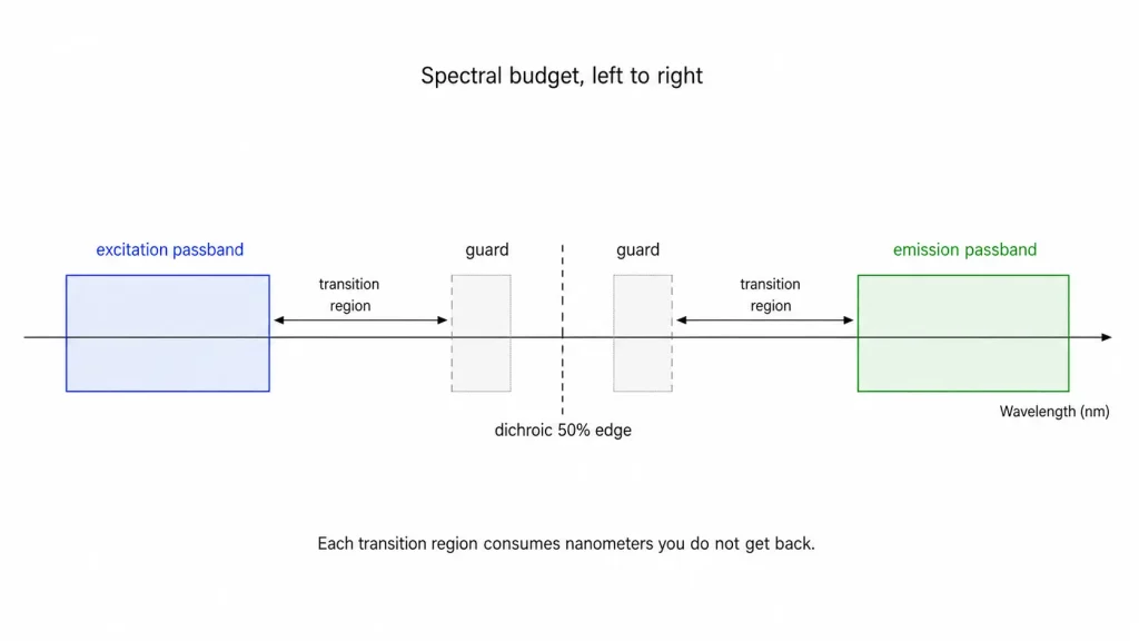
Each arrow is a transition region, and each one consumes nanometers you do not get back.
The industry convention for quantifying that cost is edge steepness: the wavelength distance from the 50% transmission point to the optical density 6 (OD 6) blocking point, expressed as a percentage of the 50% wavelength. Commercial hard-coated edge filters span roughly 0.2% for premium laser-grade parts up to about 1.5% for general-purpose grades. At 500 nm, 1% is 5 nm on one edge alone.
Add the excitation filter’s long-wavelength edge, the dichroic edge, and the emission filter’s short-wavelength edge, and a mid-grade set can consume 10 to 15 nm at 500 nm before a single signal photon is collected. Against fluorescein’s 24 nm shift, that is most of the budget. Against DAPI’s 103 nm, it is irrelevant.
Why the dichroic is usually the limiting element
At 45 degrees AOI, a thin-film edge splits into separate s-polarization and p-polarization responses. The p-edge sits at shorter wavelength, so the unpolarized transition region is broader than either alone and the passband picks up ripple. The dichroic is normally the shallowest edge in the set, and for small-Stokes-shift dyes its placement tolerance is the first thing to scrutinize.
The datasheet parameters that govern the result
| Element | Parameters to specify | Notes |
|---|---|---|
| Excitation bandpass | Center wavelength (CWL), full width at half maximum (FWHM), peak and average transmission, out-of-band blocking OD and blocking range | Blocking range must explicitly cover the emission band, not just the near sidebands |
| Dichroic beamsplitter | 50% edge wavelength at 45° AOI, reflection band, transmission band, Rs/Rp behavior, transmitted wavefront error (TWE), flatness (peak-to-valley over the clear aperture) | Specify the edge at 45°, not at normal incidence |
| Emission filter | CWL and FWHM (bandpass) or edge wavelength (longpass), average transmission, OD at the excitation wavelengths | OD6 blocking is a common target in high-contrast and laser-excited fluorescence systems, but the required blocking level depends on source power, detector sensitivity, stray light, and acceptable background. |
| All elements | AOI and half-cone angle, clear aperture, surface quality (MIL-PRF-13830B scratch-dig, or ISO 10110-7), substrate autofluorescence, thermal drift | Cone angle is routinely omitted from requests and routinely causes surprises |
Optical density is OD = −log₁₀(T), so OD 6 is one part in 10⁶. Excitation power at the sample exceeds collected fluorescence by many orders of magnitude, and blocking is what converts a bright field of scattered excitation light into a dark background.
Angle of incidence: the shift that is always there
Every dielectric filter blue-shifts as AOI increases, approximately:
λ(θ) = λ₀ × √(1 − sin²θ / n_eff²)
where n_eff is the effective index of the coating stack. For a 500 nm bandpass, a 10 degree tilt shifts the CWL by roughly 2 nm for a high-index design (n_eff ≈ 2.0) and roughly 4 nm for a lower-index design (n_eff ≈ 1.45). A converging or diverging beam shifts the passband and smears the edges at the same time, because different rays see different angles.
For a dye with a 100 nm shift, nobody notices. For Cy5, a 3 nm unplanned blue shift of the emission filter’s short-wavelength edge drops it into the excitation crossover and raises the background by orders of magnitude.
Coating technology and what it costs you
| Hard-coated (sputtered, single substrate) | Soft-coated (evaporated, often laminated) | |
|---|---|---|
| Peak transmission | Typically >90%, often >95% | Lower, and lower still in laminated stacks |
| Edge steepness | Steep; sub-1% achievable | Shallower for comparable layer counts |
| Environmental stability | Non-hygroscopic oxides; stable with humidity | Hygroscopic layers require sealing; ages |
| Deep blocking | From the dielectric stack itself | Often relies on absorbing colored glass |
| Cost | Higher per part | Lower, and simpler for wide passbands |
For large-Stokes-shift work with generous guard bands, a soft-coated set can be adequate and considerably cheaper. For small shifts, weak signals, or quantitative multiplexing, hard coatings are a requirement rather than a preference. Suppliers such as GIAI Photonics list narrow bandpass filters, dichroic filters, and longpass and shortpass filters as separate categories precisely because the specification drivers differ from one leg of the set to the next.
The core trade-offs
Narrower emission FWHM lowers background but costs signal. Collected signal scales as ∫ E(λ) · T_em(λ) · η(λ) dλ, where E is the emission spectrum, T_em the filter transmission, and η the detector quantum efficiency. Typical organic dye emission bands are 50 to 80 nm wide at FWHM. Narrowing an emission filter from 60 nm to 25 nm can cut collected photons by roughly half. Do it only when background, not photon count, limits you.
Steeper edges cost layers, and layers cost flatness. More layers means more coating stress, which bows the substrate. On a dichroic in an imaging path that bow becomes transmitted wavefront error, and in laser scanning or total internal reflection fluorescence (TIRF) it distorts the reflected excitation beam. Steepness and flatness are traded against each other on the same part.
Common specification mistakes
Specifying blocking on the wrong filter. The most expensive error in the field. The emission filter blocks the excitation band, and the dichroic reflects it. Neither can remove source light that is already at the emission wavelength. If your excitation bandpass has only OD 4 out-of-band blocking, broadband lamp or LED output leaks straight through the sample path and lands in your detection band looking exactly like signal. Blocking must be specified on the excitation filter, and its blocking range must be stated to cover the full emission band.
Placing the emission passband on the emission peak. For a 20 nm shift, centering the emission filter on the emission maximum puts its short-wavelength edge inside the excitation band’s tail. The correct move is to shift the emission passband red of the peak and accept the signal loss, or to buy a steeper edge.
Getting the angle specification wrong. A dichroic is a 45 degree part and its edge wavelength must be quoted at 45 degrees, not at normal incidence. For the bandpass elements, “AOI 0 degrees” without a stated half-cone angle is an incomplete specification for any real optical train.
Ignoring substrate autofluorescence. Filter glass fluoresces. In an emission filter sitting in the detection path, that fluorescence is indistinguishable from sample signal. For single-molecule or low-copy-number work, specify low-autofluorescence substrates and confirm with the supplier.
Forgetting the solvent Raman band. Water’s OH stretch sits near 3,400 cm⁻¹, a fixed wavenumber offset. Excite at 488 nm and the water Raman band appears near 585 nm; excite at 532 nm and it lands near 650 nm. In dilute aqueous samples this can dominate the background, and unlike autofluorescence it moves predictably. Check whether it falls inside your emission passband before you finalize the design.
Tilting a bandpass to tune it. Useful for prototyping, but tilt also broadens the passband, degrades edge steepness, and introduces polarization splitting. It is a bench technique, not a production specification.
How to choose: a working sequence
- Get the spectra for your actual conjugate in your buffer, not a generic table value.
- Compute Δλ/λ. Below roughly 4%, plan on hard-coated, steep-edge components and expect to pay for them.
- Fix the source first. A laser line collapses the excitation budget to almost nothing; a broadband LED or lamp needs an excitation bandpass with genuine out-of-band blocking.
- Place the dichroic edge between the two passbands with margin on both sides, remembering it is the shallowest edge.
- Set the emission passband width by integrating the emission spectrum against detector quantum efficiency, then check what background that width admits.
- Verify AOI and half-cone angle at every filter position in the mechanical layout.
- Specify surface quality and clear aperture. Imaging paths commonly call for 40-20 or better scratch-dig; non-imaging collection legs tolerate 60-40.
When spectral separation is not the answer
Some problems are not solvable with steeper edges. Lanthanide chelates emit on microsecond to millisecond timescales, so time-gated detection separates signal from prompt background temporally rather than spectrally. Quantum dots absorb broadly and emit narrowly, letting you excite far from the emission band. Two-photon excitation uses near-infrared photons at roughly twice the corresponding one-photon excitation wavelength, although the actual two-photon absorption maximum must be determined from the fluorophore’s measured spectrum, making the filter problem almost trivial. If a set is fighting a 15 nm shift on a weak signal, changing the probe or the excitation scheme is usually cheaper than changing the coating.
FAQ
Does a larger Stokes shift always mean a better filter set? It means an easier one. Large shifts allow wider passbands, shallower edges, and higher throughput for a given cost. They do not guarantee sensitivity, because quantum yield, extinction coefficient, photostability, and sample autofluorescence all still apply. A large-shift dye with low brightness can easily lose to a small-shift dye in a well-designed set.
When is OD6 blocking necessary? Excitation power at the sample exceeds collected fluorescence by many orders of magnitude. At OD 4, one part in 10⁴ of scattered and reflected excitation light reaches the detector, which for weak samples is comparable to or larger than the signal. OD 6 pushes that leakage below typical sample and substrate background, which is where it stops being the limiting term.
Can I use one filter set for two dyes with similar Stokes shifts? Only if you can tolerate bleed-through. Overlapping emission tails mean each channel collects some of the other dye’s photons. Multiband sets are designed for this, but they still require either spectral unmixing or acceptance of a known crosstalk fraction. For quantitative work, sequential single-band imaging remains cleaner.
How much does temperature move the passband? Hard oxide coatings drift toward longer wavelength as temperature rises, driven by dn/dT and thermal expansion. For a fluorescence bandpass 20 to 40 nm wide, the drift over a normal lab range is negligible. It becomes a real specification only for narrow laser-line and Raman filters, where the passband is a few nanometers. Ask the supplier for the coefficient if your passband is under about 10 nm.
Should the emission filter be a bandpass or a longpass? Longpass for maximum throughput with a single dye in a low-autofluorescence sample. Bandpass whenever you have a second fluorophore, significant long-wavelength sample background, or a solvent Raman band inside the collection range. When photon count is limiting and the sample is clean, the longpass usually wins.
Does the excitation filter need to sit at the absorption peak? No, and often it should not. Because emission is independent of excitation wavelength, moving the excitation band blue of the absorption peak widens the gap to the emission band at the cost of some excitation efficiency. For tight-shift dyes this trade is frequently worth making, since background scales with leakage while signal scales only linearly with excitation efficiency.
For excitation, beamsplitting, and emission legs, the relevant component categories are narrow bandpass filters, dichroic filters, and longpass and shortpass filters, all of which GIAI Photonics supplies as standard and custom-coated parts.
