
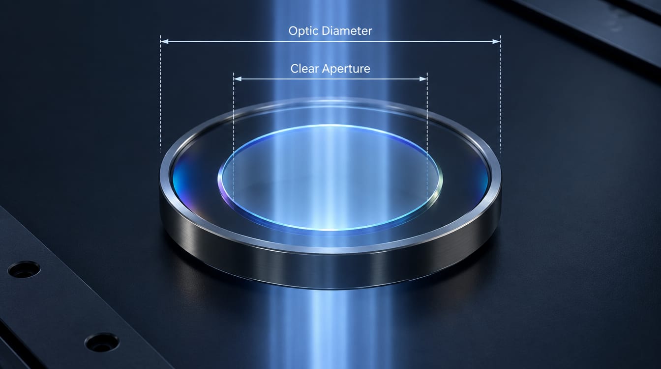
Optic diameter is the physical outside diameter of a circular optical component. Clear aperture is the region of that optic over which specified optical performance is required. The clear aperture is therefore usually smaller than the physical diameter, because part of the edge may be reserved for bevels, mounting, handling, coating transitions, or manufacturing edge effects.
This distinction matters when specifying lenses, windows, filters, mirrors, and other precision optical components. A part can have the correct outside diameter while still providing insufficient usable optical area for the beam.
In common optical specification practice, the clear aperture defines the region that is required to meet the stated optical specifications; performance outside that region is not necessarily guaranteed.
Clear Aperture vs Optic Diameter at a Glance
| Parameter | Optic Diameter | Clear Aperture |
|---|---|---|
| What it describes | Physical outside size | Usable specified optical region |
| Primary purpose | Mechanical fit and geometry | Optical performance |
| Typical notation | ØD, Diameter | CA, Clear Aperture |
| Includes edge zone? | Yes | Usually no |
| Relevant to mounting? | Directly | Indirectly |
| Relevant to beam passage? | Not sufficient by itself | Yes |
| May have its own tolerance? | Yes | Yes |
| Same as coated area? | Not necessarily | Not necessarily |
| Same as beam diameter? | No | No |
The important engineering point is that diameter and clear aperture should be treated as two separate requirements, not as interchangeable dimensions.
What Is Optic Diameter?
For a round optical component, the optic diameter is the mechanical outside diameter after the part has been shaped and edged.
For example, a drawing may define:
Optic diameter: Ø25.0 mm
That dimension determines whether the component fits into a lens barrel, retaining ring, cell, filter wheel, or other mechanical interface. Diameter tolerance therefore belongs primarily to the mechanical definition of the component.
A diameter specification by itself does not tell the optical designer how much of the surface is guaranteed to meet requirements for surface quality, transmitted wavefront, flatness, coating performance, or another optical characteristic.
GIAI’s project review likewise treats component diameter and clear aperture as separate geometry inputs alongside thickness, radius, wedge, angle, and mechanical interfaces.
What Is Clear Aperture?
The clear aperture, or CA, is the defined region of the optical surface intended to satisfy the specified optical requirements.
For a circular optic, it may be specified as an explicit diameter:
Clear Aperture: Ø22.5 mm minimum
or as a percentage of the physical diameter:
Clear Aperture: ≥90% of diameter
For a rectangular window or filter, the clear aperture may instead be specified as a usable width and height.
The region outside the clear aperture is still physically part of the optic. However, unless the drawing states otherwise, it should not automatically be assumed to meet all of the same optical requirements as the specified clear region.
This distinction gives the manufacturer a controlled edge zone for features or process effects that may include bevels, mounting contact, polishing edge effects, coating masking, or handling.
Why Is Clear Aperture Usually Smaller Than the Optic Diameter?
Making the clear aperture smaller than the physical optic is not simply wasted area. The difference often serves an engineering purpose.
Consider a nominal Ø25 mm lens with a Ø22.5 mm clear aperture. The radial edge allowance is:
So the optic retains a 1.25 mm peripheral zone around the specified optical region.
That space may be needed for edge finishing, mechanical retention, manufacturing fixtures, or areas where optical specifications are more difficult to control all the way to the physical edge.
The exact allowance should come from the actual optical and mechanical design rather than from a universal percentage.
Be Careful With “90% Clear Aperture”
A specification such as “CA ≥90%” can be ambiguous unless it states whether the percentage refers to diameter or area.
For a circular optic:
means that a 25 mm optic has:
But a clear aperture that is 90% of the diameter provides only:
or 81% of the total circular area.
Conversely, if the real requirement is 90% of the total area, the clear-aperture diameter would need to be approximately:
This is why an explicit dimensional requirement such as “Clear Aperture: Ø22.5 mm min.” is generally clearer than simply writing “90% CA.”
Clear Aperture Is Not the Same as Beam Diameter
Another common mistake is selecting an optic whose clear aperture is exactly equal to the nominal beam diameter.
The optical beam should generally fit inside the clear aperture with sufficient margin for system tolerances such as beam decenter, component decenter, angular alignment, assembly variation, and beam-size uncertainty.
Suppose a system has a nominal 20 mm collimated beam and uses the earlier Ø22.5 mm clear aperture. At normal incidence, the nominal radial margin is only:
Whether that is enough depends on the alignment and mechanical tolerance budget.
A design should therefore start with the worst-case beam footprint, not simply the nominal beam diameter.
Angle of Incidence Can Increase the Required Aperture
Clear-aperture requirements become especially important when an optic is tilted.
For a circular collimated beam striking a flat optic at an angle of incidence , a useful first-order geometric approximation for the footprint along the plane of incidence is:
For an illustrative 20 mm beam at 30°:
A Ø22.5 mm clear aperture that appears sufficient at normal incidence would therefore be too small for this simplified tilted-beam case.
This example assumes a collimated circular beam and simple flat-surface geometry. Converging beams, divergent beams, Gaussian beam definitions, decentered systems, prisms, curved surfaces, and multi-element systems require a more complete optical analysis.
Clear Aperture vs Mount Aperture
The optic itself is not the only aperture in the system.
A mounted component can involve at least three different dimensions:
Optic diameter → optic clear aperture → mechanical opening in the mount
If the mount opening is smaller than the optical clear aperture, the mount can become the limiting aperture and may clip the beam.
If the mount opening is larger than the specified clear aperture, that does not automatically extend the region over which the optic’s specified performance applies.
This is why the optical and mechanical drawings should be reviewed together.
Clear Aperture Is Also Not Necessarily the Coated Area
For coated optics, three regions may be different:
physical surface size, coated area, and specified clear aperture.
A coating may extend beyond the clear aperture, stop before the physical edge, or use an edge exclusion defined by the manufacturing process. The important requirement is whether the specified transmission, reflection, blocking, or other coating performance must be achieved across the required clear aperture.
Avoid assuming that “fully coated” and “100% clear aperture” mean the same thing.
What Should an Optical Drawing Specify?
A robust drawing should define the clear aperture in a way that can be manufactured and inspected without interpretation.
For a critical optical component, useful inputs can include:
- Physical diameter or outside dimensions and tolerance
- Minimum clear-aperture dimension
- Location or concentricity of the clear aperture when relevant
- Surface or wavefront requirement and the region over which it applies
- Surface-imperfection requirement and applicable region
- Coating performance within the required aperture
- Beam diameter or footprint where it affects component selection
- Nominal and maximum AOI
- Mechanical mount opening and alignment allowances
ISO 10110 establishes a standardized framework for presenting optical-element characteristics and tolerances on technical drawings and includes concepts such as test regions and test fields. The current ISO 10110-1:2019 edition was reconfirmed in 2025.
For demanding parts, it is also important not to assume that every optical characteristic is evaluated over the same region. The drawing or agreed inspection specification should make the relevant test area clear.
How Clear Aperture Affects Inspection
Diameter inspection and clear-aperture inspection answer different questions.
Diameter inspection asks:
Does the finished part meet its mechanical geometry?
Clear-aperture-related inspection asks:
Does the required region satisfy the optical or surface requirements defined for that region?
Depending on the component, project inspection may include dimensions, coating area, surface condition, appearance, clear aperture, and other drawing-controlled features. GIAI’s manufacturing and quality reference explicitly treats external dimensions and clear aperture as separate inspection considerations.
This distinction becomes especially important for precision windows, filters, lenses, and mirrors where only a defined central region is used by the optical system.
Common Specification Mistakes
Several problems repeatedly appear when clear aperture is not defined carefully.
One is specifying only the physical diameter and assuming the entire surface is usable. Another is writing “90% CA” without saying whether that means diameter or area. Designers may also match the beam diameter exactly to the clear aperture without accounting for decenter, tilt, or assembly tolerance.
Other problems include assuming that the mount opening equals the optic clear aperture, assuming the coating automatically satisfies specification to the physical edge, or requesting surface and wavefront performance without defining the region over which those requirements apply.
All of these problems can be reduced by defining the mechanical size and optical usable region separately.
Specifying Clear Aperture for a Custom Optical Component
For custom optics, the required clear aperture should come from the actual optical path rather than from an arbitrary percentage of the component diameter.
GIAI Photonics supports project-based review of optical filters, lenses, prisms, windows, mirrors, beamsplitters, infrared optics, coated optics, and applicable optical assemblies.
For a custom project, provide the drawing or sample together with the material, overall dimensions, minimum clear aperture, wavelength range, coating requirements, AOI, beam geometry, relevant surface or wavefront requirements, inspection criteria, and expected quantity. GIAI reviews geometry and clear-aperture requirements together with the intended optical function before the manufacturing and inspection route is defined.
4. FAQ
Is clear aperture always smaller than optic diameter?
Usually, but it does not have to follow one fixed percentage. The required difference depends on edge geometry, mounting, manufacturing process, coating requirements, beam size, and the optical specifications that must be maintained near the edge.
Does 90% clear aperture mean 90% of the optical area?
Not necessarily. If it means 90% of the diameter of a circular optic, the resulting clear area is approximately 81% of the total area. Specify the clear-aperture dimension explicitly when ambiguity would affect the design.
Can the beam diameter equal the clear aperture?
It is generally safer to include margin. Beam position, optic decenter, mounting tolerance, beam divergence, and angle of incidence can all increase the required usable area. The appropriate margin should come from the system tolerance budget.
Does clear aperture define coating performance?
Only if the specification states that the coating requirement applies over that region. Coated area and clear aperture are related but distinct parameters and should be defined separately when necessary.
Should clear aperture be specified on the optical drawing?
For optics where usable area affects system performance, yes. An explicit clear-aperture dimension makes manufacturing and inspection requirements much clearer than relying on the outside diameter alone.