
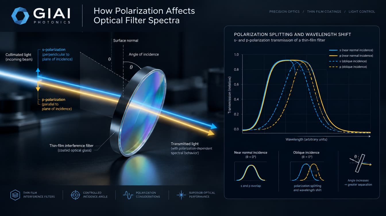
Polarization can change the measured transmission or reflection spectrum of an optical interference filter, especially when the filter operates at a non-normal angle of incidence. At oblique incidence, s-polarized and p-polarized light no longer interact with the multilayer coating in exactly the same way. Their spectral features can shift by different amounts, creating polarization-dependent changes in center wavelength, edge position, bandwidth, peak transmission, blocking, and overall spectral shape.
For a filter used near normal incidence, polarization effects may be small. For a narrow bandpass filter, steep edge filter, dichroic, or beamsplitter operated at an appreciable angle, polarization can become a first-order design parameter.
Why Does Polarization Change an Optical Filter Spectrum?
For a conventional dielectric interference filter, spectral filtering is produced by constructive and destructive interference between reflections from multiple thin-film interfaces. The optical phase accumulated in each layer depends on wavelength, layer thickness, refractive index, and propagation angle inside the layer.
At normal incidence, an isotropic multilayer has rotational symmetry around the surface normal, so the s- and p-polarized responses converge. Once the beam is tilted, that symmetry is lost.
The two polarization states are defined relative to the plane of incidence:
- s-polarization: the electric field is perpendicular to the plane of incidence.
- p-polarization: the electric field lies in the plane of incidence.
The Fresnel reflection and transmission coefficients are different for these two states at oblique incidence. In a multilayer coating, those polarization-dependent interface responses combine with polarization-dependent phase behavior throughout the stack. As a result, the complete filter spectrum calculated for s-polarization is generally different from that calculated for p-polarization.
This is why stating only that a filter operates at, for example, a certain AOI may be insufficient. The polarization state can also matter.
AOI Causes Spectral Shift — Polarization Causes the Shift to Split
For many conventional interference filters, increasing the angle of incidence shifts spectral features toward shorter wavelengths. A commonly used first-order approximation is:
where:
- is the spectral feature at the reference incidence angle,
- is its approximate position at angle ,
- is the refractive index of the incident medium,
- is an effective refractive index describing the filter,
- is the external angle of incidence.
This equation is useful for understanding the familiar blue shift of an interference filter as AOI increases. It is not, however, a complete polarization model. The effective optical behavior is design-, wavelength-, and polarization-dependent, so accurate s- and p-spectra normally require the actual thin-film design or a polarization-aware multilayer calculation.
At non-normal AOI, the result is therefore not simply “the same spectrum shifted left.” Instead, two related but different spectra can emerge:
s-polarized spectrum
and
p-polarized spectrum
The wavelength separation between corresponding s and p features is often called polarization splitting. Optical thin-film research has experimentally and theoretically demonstrated this separation in filters operated at oblique incidence.
What Parts of the Spectrum Can Change?
Polarization dependence is not limited to center wavelength. Depending on filter design and AOI, several spectral characteristics may change.
| Spectral characteristic | Possible polarization effect | Why it matters |
|---|---|---|
| Center wavelength / peak position | s and p peaks may occur at different wavelengths | Signal wavelength may no longer align equally with both polarization states |
| Cut-on or cut-off wavelength | Edge positions may split | Important for steep longpass, shortpass and dichroic filters |
| FWHM / passband width | s and p bandwidths may differ | Can change collected signal or spectral selectivity |
| Peak / average transmission | Transmission can differ between s and p | Produces polarization-dependent signal level |
| Blocking / notch depth | Rejection may become polarization-dependent | Critical when unwanted light is much stronger than the wanted signal |
| Spectral shape | Passbands or edges may become asymmetric or distorted | A single nominal CWL or edge value may no longer describe performance adequately |
There is no universal rule that p-polarization always shifts farther than s-polarization for every filter and every spectral feature. The result depends on the multilayer design. For example, different bandpass, longpass, shortpass and notch designs can exhibit different polarization-dependent shifts and bandwidth changes.
That design dependence is important when specifying custom filters: an AOI value alone does not predict the complete spectrum.
How Different Polarization States Appear in a Measured Spectrum
The distinction between s and p becomes particularly useful when translating coating behavior into an actual optical system.
Linearly Polarized Light
If the incident light is purely s-polarized, the relevant spectrum is . For purely p-polarized light, it is .
For linearly polarized light oriented between the two axes, and assuming an isotropic non-depolarizing filter, its intensity response can be considered as the weighted contribution of the two components:
where is the polarization angle measured from the s direction.
This is why specifying a laser as merely “linearly polarized” may not be enough. Its polarization orientation must be defined relative to the filter’s plane of incidence.
Unpolarized Light
For an equal incoherent mixture of s and p components, the intensity spectrum is commonly represented by:
When the two spectra are almost identical, this average is straightforward. When polarization splitting is large, however, the averaged curve can develop broader transitions, shoulders, or other features that are not present in either individual polarized spectrum.
Circular or Elliptically Polarized Light
Circularly polarized light can also be decomposed into s and p components. If a filter introduces different amplitudes or phases for those components, the transmitted polarization state can change.
Therefore, an application concerned only with detector intensity may primarily require and , while an interferometric or polarization-sensitive system may also need information about relative phase, not merely transmission percentage.
Which Optical Filters Are Most Sensitive to Polarization?
Narrow Bandpass Filters
Narrowband filters can be particularly sensitive because a relatively small displacement of the s- or p-spectrum may represent a significant fraction of the required bandwidth.
For a laser, fluorescence channel, spectroscopy system, or narrow spectral sensor, it is therefore risky to verify only a nominal CWL at one unspecified polarization if the operating AOI is non-normal.
Longpass and Shortpass Filters
With steep edge filters, polarization splitting may produce different cut-on or cut-off wavelengths for s and p components.
An unpolarized measurement can then show a broader-looking transition or a shoulder around the edge even though each individual polarization has a steeper transition. The exact behavior remains design-dependent.
Dichroic Filters and Beamsplitters
Polarization becomes especially important for dichroic mirrors and plate beamsplitters because these components are frequently operated at substantial AOI.
At such geometry, the coating designer may need to:
- minimize the difference between s and p,
- specify acceptable performance separately for both,
- optimize for one known polarization,
- or deliberately create a strong polarization difference.
Thin-film designs can in fact be engineered specifically to reduce or exploit polarization dependence.
Notch Filters
For a notch filter, polarization can affect more than the notch wavelength. The rejection depth and notch width may also vary with AOI and polarization, depending on the coating architecture.
If a strong laser line must be rejected while a much weaker neighboring signal is detected, this difference can become more important than a small change in nominal center wavelength.
Absorptive Filters
An isotropic bulk absorptive filter does not derive its primary spectral shape from multilayer interference, so its bulk absorption spectrum is generally less subject to the same s/p spectral splitting mechanism.
However, surface reflections, AR coatings, anisotropic materials, or additional interference coatings can still introduce polarization-dependent behavior. It is therefore better to identify the actual filter construction rather than assume that every “optical filter” responds in the same way.
AOI Is Not the Only Angular Variable
A common engineering mistake is to specify one AOI while ignoring the angular distribution of the beam.
A collimated beam incident at a single angle is relatively straightforward. A converging or diverging beam contains a range of incidence angles. Each ray may therefore experience a slightly different spectral response.
This matters in:
- high-NA imaging systems,
- wide-field cameras,
- fluorescence optics,
- machine vision lenses,
- compact sensor modules,
- light collection systems,
- filters positioned close to a focal plane.
The angular range is sometimes described using a cone half-angle (CHA). Filter modeling should consider both the nominal AOI and the beam cone when the angular spread is significant.
There is an additional polarization complication: the plane of incidence changes with ray direction. A fixed linear polarization in system coordinates therefore does not necessarily correspond to the same s/p mixture for every ray in a wide angular cone.
In such systems, one single “s spectrum” or “p spectrum” at one AOI may still be insufficient.
Common Specification Mistakes
Several filter problems that initially look like coating errors are actually specification or system-integration problems.
Testing at 0° but operating the filter tilted.
A spectrum measured near normal incidence may not represent the installed component.
Specifying AOI but not polarization.
This is particularly problematic when the source is a polarized laser or the filter is used as a tilted dichroic.
Calling polarization “horizontal” or “vertical” without defining system geometry.
s and p are defined relative to the plane of incidence. A mechanical horizontal/vertical description can become ambiguous when the filter orientation changes.
Using an average-polarization curve to evaluate a polarization-sensitive system.
The average spectrum may hide substantial differences between and .
Ignoring the illumination cone.
A filter evaluated with collimated light may behave differently in a converging beam.
Specifying only CWL or FWHM.
For a demanding system, passband transmission, blocking range, edge positions, AOI, polarization and measurement conditions can be equally important.
How Should Polarization Be Specified for an Optical Filter?
For a polarization-sensitive interference filter project, a useful specification should define the operating geometry rather than simply requesting a wavelength.
Typical inputs include:
- required passband, CWL, edge wavelength or spectral function;
- transmission and reflection targets;
- required blocking range and OD where applicable;
- nominal AOI;
- acceptable AOI range;
- beam cone or numerical aperture if relevant;
- polarization state: s, p, unpolarized, circular, or a defined linear orientation;
- whether the requirement applies independently to both s and p;
- allowable s/p wavelength splitting or polarization-dependent transmission, if critical;
- substrate and component dimensions;
- clear aperture;
- source spectrum or laser wavelength;
- detector spectral response;
- operating environment;
- inspection and spectral measurement conditions.
Polarization is explicitly one of the engineering variables that may need to be defined together with wavelength, AOI, spectral targets, substrate and inspection requirements in a custom filter or coating project.
How Should Polarization-Dependent Filter Performance Be Verified?
If polarization matters in the final system, verification should reproduce the relevant operating conditions as closely as practical.
For example, instead of accepting only one unspecified transmittance curve, an engineer may request:
- at the application AOI;
- at the same AOI;
- average-polarization data if that is also relevant;
- polarization-dependent peak or average transmission;
- s/p edge or CWL separation;
- spectral behavior across the required AOI range;
- test geometry and measurement conditions.
For wavelength-selective optical components, GIAI’s project guidance emphasizes that spectral verification should be tied to the agreed specification and measurement conditions; AOI is specifically relevant because the spectrum of an interference filter can change with incidence angle.
The same principle applies to polarization: a measurement that does not reproduce the required polarization state cannot fully verify a polarization-dependent specification.
Polarization Should Be Treated as Part of the Optical System
The practical question is not simply:
“Is this filter polarization sensitive?”
A better engineering question is:
At the actual AOI, beam geometry, wavelength range and polarization state of the system, are the differences between the s and p spectra small enough for the application?
Sometimes they are.
Sometimes the design must be optimized to minimize polarization splitting.
And sometimes different s and p behavior is intentional, as in a polarizing beamsplitter.
What matters is that polarization, AOI and spectral requirements are defined together rather than evaluated independently.
Custom Optical Filter and Coating Review
GIAI Photonics supports optical filters, beamsplitters, optical coatings and other custom optical components as project-specific engineering requirements. For custom projects, the manufacturing and inspection route is reviewed against the drawing or sample, optical requirements, substrate, geometry, coating conditions and inspection criteria rather than assuming one standard specification applies to every part.
For a polarization-sensitive filter inquiry, provide the target spectrum together with AOI, polarization state, beam geometry, substrate, dimensions, coating requirements, blocking requirements and measurement criteria. This allows the spectral requirement to be evaluated under conditions closer to the intended optical system.
4. FAQ
Does polarization affect an optical filter at normal incidence?
For an isotropic dielectric multilayer at ideal normal incidence, the s- and p-polarized responses converge, so polarization dependence is generally much smaller than at oblique incidence. Exceptions can occur with intentionally polarizing structures, anisotropic materials or other polarization-sensitive optical architectures.
Why do s- and p-polarized filter spectra separate at an angle?
At oblique incidence, s and p waves have different Fresnel coefficients and optical admittances at the interfaces within the multilayer. Their accumulated interference conditions are therefore no longer identical. The result can be different spectral positions, bandwidths, transmissions or blocking characteristics.
Does p-polarization always shift more than s-polarization?
No. The direction and magnitude of the difference depend on the multilayer design and on which spectral feature is being evaluated. It is safer to obtain or calculate separate s and p spectra for the intended AOI than to apply a universal rule.
Is an unpolarized spectrum enough for a polarized laser system?
Usually not if polarization dependence is significant. An average-polarization spectrum can conceal differences between s and p. For a linearly polarized laser, the filter should be evaluated for the actual polarization orientation relative to the plane of incidence.
Can polarization change optical density or blocking?
Yes. At oblique incidence, polarization can modify the rejection spectrum as well as the passband. Depending on the filter design, notch depth, blocking level or blocking edge may differ between s and p. Blocking should therefore be verified under the polarization and AOI conditions specified by the application.
Does a converging beam make polarization effects worse?
It can make the spectral behavior more complicated because the filter receives a distribution of AOIs rather than one incidence angle. Each ray can also have a different plane of incidence, changing the local s/p decomposition. High-NA or wide-angle systems therefore benefit from angle- and polarization-aware modeling.