
- A collimated N-BK7 plano-convex lens with f = 50 mm reaches the 0.07 λ RMS diffraction limit at f/6.4 (computed, 587.6 nm).
- Face the curved side of a plano-convex lens toward the collimated beam; reversing it quadruples computed longitudinal spherical aberration.
- An asphere corrects on-axis spherical aberration for one wavelength, conjugate and orientation. It does not fix chromatic focal shift or off-axis coma.
- Aspheres move complexity into the part: tighter centration, harder metrology and a drawing that must define the sag equation and sign convention.
- Choose by f-number, field of view, spectral bandwidth and alignment budget before choosing a surface type.
An aspheric lens uses a surface whose curvature changes from center to edge, so at its design wavelength it can bring a collimated beam to a single on-axis focus. A plano-convex lens uses a spherical surface, so its marginal rays focus closer to the lens than its paraxial rays. At slow f-numbers the difference is negligible. At fast f-numbers it dominates the spot size.
The comparison is less about lens outline than about surface type. Many aspheric singlets are themselves plano-convex in form, with one flat side and one aspheric side. The practical question is therefore when a spherical convex surface stops being good enough, and what the asphere costs in alignment, inspection and specification effort. For related topics on lens geometry, tolerances and surface specification, see our lens and optical component guides.
What is the difference between an aspheric lens and a plano-convex lens?
A plano-convex lens has one flat surface and one spherical surface with a single radius of curvature. An aspheric lens has at least one surface whose local curvature varies with distance from the optical axis. That surface is described by a sag equation rather than by one radius.
The most common description is the even asphere:
z(r) = c·r² / [1 + √(1 − (1 + k)·c²·r²)] + A4·r⁴ + A6·r⁶ + …
Here z is the surface sag at radial height r, c = 1/R is the vertex curvature, k is the conic constant and A4, A6 and so on are polynomial coefficients. With k = 0 and all coefficients zero, the equation reduces to a sphere. Orthogonal polynomial forms, such as the Q-type descriptions introduced by Forbes, are also used because their coefficients are easier to tolerance and less prone to numerical cancellation.
Surface type defines what each lens can correct:
- A spherical surface has no unique axis. Any line through its center of curvature is an axis of symmetry.
- An aspheric surface has exactly one axis of symmetry. That axis must be aligned to the beam and to the opposite surface.
This distinction drives the tolerancing differences discussed below.
Why does a plano-convex lens produce spherical aberration?
A spherical surface refracts marginal rays more strongly than the paraxial approximation predicts. In a positive plano-convex lens, rays near the edge of the aperture therefore cross the axis before the paraxial focus. The axial distance between the marginal and paraxial crossing points is longitudinal spherical aberration (LSA). It is set by the surface shape, not by fabrication error.
In third-order theory, the aperture dependence follows fixed power laws:
- LSA grows with the square of ray height.
- Transverse blur grows with the cube of ray height.
- Wavefront error grows with the fourth power of ray height.
Halving the f-number of a given lens therefore raises its spherical wavefront error by a factor of 16. For the same f-number, the wavefront error in waves also scales in proportion to focal length and inversely with wavelength.
Orientation matters because it controls how refraction is shared between the two surfaces. For focusing a collimated beam, the curved surface should face the beam and the flat surface should face the focus. Both surfaces then bend the rays, and neither carries the full deviation. For a glass index near 1.5 at infinite conjugate, this orientation is close to the minimum-aberration shape available to a spherical singlet. Reversing the lens, so that the flat side faces the collimated beam, puts all the refraction on the curved surface. In the ray trace below, that raises LSA by a factor of 4.
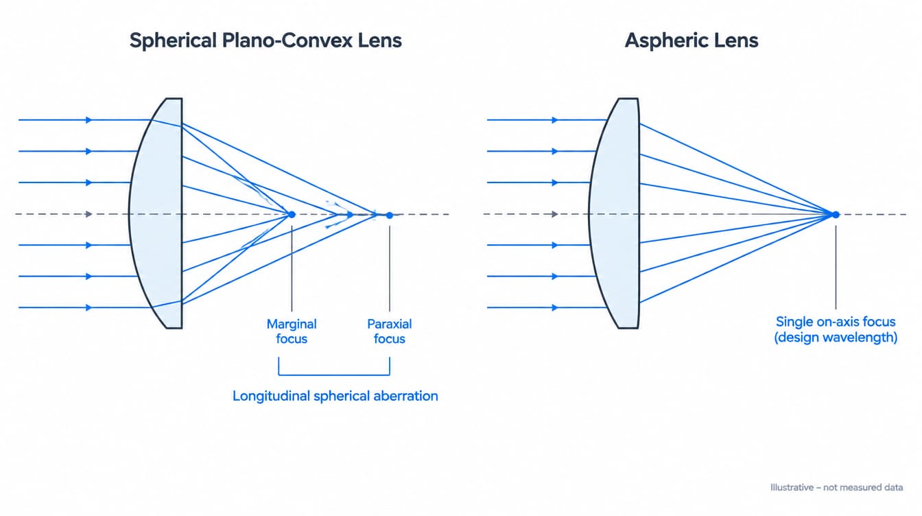
At what f-number does a plano-convex lens stop being diffraction-limited?
For a given focal length and wavelength, a plano-convex lens is diffraction-limited up to a certain beam diameter and aberration-limited beyond it. Under the conditions below, the computed crossover is f/6.4 (a 7.8 mm beam diameter). This uses the Maréchal criterion, an RMS wavefront error of 0.07 λ. At slower f-numbers an asphere adds little to on-axis focus quality.
Calculation conditions:
- Lens: N-BK7, nd = 1.5168 at 587.6 nm, convex radius 25.84 mm, center thickness 5.5 mm, effective focal length 50 mm.
- Beam: monochromatic, collimated and on-axis, filling the stated diameter.
- Method: exact ray trace. RMS wavefront error is area-weighted over the pupil after removing piston and defocus (best focus). The Airy diameter is the diameter to the first dark ring, 2.44·λ·N.
These are calculated values for an ideal lens, not measured product data.
| Configuration | Beam diameter | f-number | LSA (mm) | RMS WFE (λ) | Airy diameter (µm) |
|---|---|---|---|---|---|
| Plano-convex, curved side to beam | 5 mm | f/10 | 0.135 | 0.012 | 14.3 |
| Plano-convex, curved side to beam | 10 mm | f/5 | 0.544 | 0.19 | 7.2 |
| Plano-convex, curved side to beam | 20 mm | f/2.5 | 2.25 | 3.3 | 3.6 |
| Plano-convex, flat side to beam | 5 mm | f/10 | 0.541 | 0.043 | 14.3 |
| Plano-convex, flat side to beam | 10 mm | f/5 | 2.19 | 0.72 | 7.2 |
| Plano-convex, flat side to beam | 20 mm | f/2.5 | 9.30 | 13.7 | 3.6 |
| Plano-hyperbolic asphere, flat side to beam | 5–20 mm | f/10–f/2.5 | 0 (geometric) | 0 (geometric) | 14.3–3.6 |
The numbers show how the regime changes with aperture:
- At f/10, the geometric RMS spot radius of the correctly oriented lens is 1.1 µm, far inside the 14.3 µm Airy disk. Diffraction sets the focus.
- At f/2.5, the RMS spot radius at best focus is 79 µm against a 3.6 µm Airy diameter. Spherical aberration sets the focus, and a faster lens of the same type gets worse, not better.
The crossover is not a universal number. With the lens scaled proportionally, third-order scaling gives a crossover f-number proportional to (f/λ)1/4. Doubling the focal length at the same wavelength moves the crossover in this example from f/6.4 to f/7.6. Glass index also shifts it: for the same focal length and aperture, a higher-index material needs shallower curvature and produces less spherical aberration. This is one reason spherical singlets in high-index infrared materials such as silicon and germanium behave differently from glass lenses at the same f-number.
The last row of the table shows the reference case for an asphere. A plano-convex lens whose convex surface is a hyperboloid with conic constant k = −n² (k = −2.301 for n = 1.5168) and no higher-order terms focuses a collimated beam entering the flat side without geometric spherical aberration at the design wavelength. This is a textbook Cartesian-surface result, confirmed by the same ray trace. Its correct orientation is the opposite of the rule for the spherical plano-convex lens. The orientation of an asphere is set by its design, not by the spherical rule of thumb.
What does an aspheric lens not correct?
An aspheric singlet corrects on-axis spherical aberration for one wavelength, one pair of conjugates and one orientation. It leaves chromatic aberration unchanged. When the aspheric surface sits at or very close to the aperture stop, it also leaves third-order coma and astigmatism where the lens bending placed them. These limits decide many real selections.
Chromatic focal shift
A singlet of one glass has a focal length that changes with refractive index across the band. In the thin-lens approximation, the focal shift between the F (486.1 nm) and C (656.3 nm) lines equals the focal length divided by the Abbe number. For the N-BK7 lens above (Vd = 64.17, nF = 1.52238, nC = 1.51432), the calculated focal lengths are 49.47 mm and 50.24 mm. That is a 0.78 mm shift, and it is the same for a spherical or aspheric lens of the same material and focal length.
Compare that shift with the diffraction depth of focus of ±2·λ·N², which is ±7.3 µm at f/2.5 and 587.6 nm (calculated). With a broadband source at a fast aperture, color dominates the focus and correcting spherical aberration alone does not recover it. Such systems need an achromatic doublet, an aspheric achromat, a diffractive-refractive hybrid or reflective optics.
Off-axis field
An aspheric term on a surface at the stop changes third-order spherical aberration only. With spherical aberration removed, coma becomes the leading error as soon as the object point moves off axis. Aspheric singlets therefore suit on-axis tasks:
- Laser diode collimation
- Fiber coupling
- Focusing a laser beam to a spot
- Light collection in condensers
Imaging across a field usually needs more than one element.
Conjugates and orientation
An asphere designed for an infinite conjugate carries residual spherical aberration when used for finite-conjugate imaging, such as 1:1 relay. Mounted backward, it can perform worse than a correctly oriented spherical lens. The design conjugates and the orientation must be known before an aspheric lens can be expected to deliver its computed performance.
How do aspheric and plano-convex lenses compare side by side?
The comparison below is qualitative. Actual performance depends on the prescription, the aperture and the tolerances of the specific design, so the entries describe behavior rather than guaranteed values.
| Lens option | On-axis SA | Chromatic error | Off-axis field | Alignment sensitivity | Surface metrology |
|---|---|---|---|---|---|
| Plano-convex, curved side to beam | Low at slow f-numbers, grows as aperture⁴ | Uncorrected | Low coma at infinite conjugate | Low | Test plate or interferometer with reference sphere |
| Plano-convex, flat side to beam | 4× higher LSA than correct orientation | Uncorrected | Worse than correct orientation | Low | Same as above |
| Aspheric singlet | Corrected at design wavelength and conjugate | Uncorrected | Limited by coma | High: tilt and decenter of the aspheric axis | Profilometry, CGH null or stitching interferometry |
| Two plano-convex lenses | Reduced by splitting power | Uncorrected | Moderate | Moderate: two elements to align | Spherical surfaces only |
| Achromatic doublet | Corrected for its design aperture | Corrected at two wavelengths | Moderate | Moderate: set by cementing | Spherical surfaces only |
What are the trade-offs of choosing an aspheric lens?
An asphere moves complexity out of the optical system and into the component. One aspheric element can replace a group of spherical elements in an on-axis design. In exchange, it needs a more involved fabrication route, a tighter centration budget, more demanding inspection and a more complete drawing.
Fabrication route
A spherical surface has constant curvature, so a full-aperture lap stays in contact with it in any position. This allows conventional grinding and polishing, often with several lenses mounted together in one block. An aspheric surface has curvature that varies across the aperture, so a full-aperture lap no longer fits it. Production relies on other routes:
- CNC generation followed by deterministic sub-aperture polishing
- Precision glass molding with dedicated tooling, restricted to moldable glass types
- Polymer injection molding
- Single-point diamond turning for crystalline infrared materials such as germanium, silicon and ZnSe, and for polymers
Each route sets its own limits on material, diameter, aspheric departure and batch size. Those limits are part of the fabrication and coating route review for any specific part.
Centration and tilt
Because a sphere has no unique axis, a small misalignment of a spherical lens mainly shifts or tilts the output beam. An aspheric surface has one axis, so misalignment affects image quality directly:
- Tilt of the aspheric axis relative to the opposite surface, or decenter relative to the mount, introduces coma and astigmatism even for an on-axis beam.
- For a plano-aspheric lens, a lateral offset of the asphere relative to the flat face is optically neutral. Tilt of the aspheric axis relative to the flat-face normal is not, and neither is decenter of the aspheric axis relative to the mechanical axis that sets the lens in its mount.
Centering tolerances belong on the drawing and should come from a tolerance analysis of the actual design.
Metrology and acceptance
Spherical surfaces are routinely checked with test plates or a Fizeau interferometer and a reference sphere. Aspheric surfaces need other methods:
- Contact or optical profilometry
- Interferometry with a computer-generated hologram (CGH) null
- Sub-aperture stitching interferometry
Measurement difficulty increases with departure from the best-fit sphere and with local slope. Acceptance criteria should state the evaluation aperture, the form deviation metric (PV, RMS or slope) and the measurement method. These are the points that inspection and acceptance criteria have to settle before production. ISO 10110-12 covers the indication of aspheric surfaces on optical drawings, alongside ISO 10110-5 for surface form tolerances and ISO 10110-6 for centering tolerances.
How to choose between an aspheric lens and a plano-convex lens
Start from the aperture, bandwidth and field, then choose the surface type. A plano-convex lens is the lower-risk choice whenever its computed wavefront error at the working f-number is already inside the budget. An asphere earns its place when spherical aberration at a fast aperture is the dominant error and the beam stays close to the axis.
- A plano-convex lens usually fits when:
- The beam fills only part of the aperture, so the working f-number is slow.
- The source is broadband, so chromatic focal shift dominates.
- The mount offers limited centration control.
- The lens is used for coarse focusing or light collection with no tight spot-size requirement.
- An aspheric lens usually fits when:
- A monochromatic or narrowband beam must reach a diffraction-limited spot at a fast f-number or high numerical aperture.
- The task is on axis, as in laser diode collimation, fiber coupling or the focusing optics used in laser beam delivery.
- Space or weight rules out a multi-element spherical group.
- Consider another option when:
- The field is wide, which calls for a multi-element design.
- The band is wide at a fast aperture, which calls for an achromatic doublet or reflective optics.
- A finite-conjugate relay is needed. Two plano-convex lenses with their curved faces toward each other often suffice here.
Both lens types are available among our precision optical lenses. The drawing, not the catalog category, should define the surface.
What mistakes are common when specifying these lenses?
Most problems come from missing conditions rather than from the lens type itself. The following errors recur in drawings and RFQs for both spherical and aspheric lenses.
- Mounting a plano-convex lens backward. Placing the flat side toward a collimated beam raises spherical aberration fourfold in the example above.
- Applying the spherical orientation rule to an asphere. The correct orientation of an aspheric lens is set by its design and should be marked on the drawing.
- Using an asphere away from its design conjugate or wavelength. Correction holds only at the design conditions.
- Leaving the sag equation incomplete. The drawing must state:
- The sign convention.
- Whether the radius or the curvature is given.
- The coefficient units, and the normalization radius for polynomial forms.
- Specifying aspheric form only as a PV value. Without an evaluation aperture and a slope or mid-spatial-frequency limit, a surface can pass PV and still scatter or blur.
- Specifying an asphere where the beam underfills the aperture. If the working f-number is slower than the crossover, the asphere adds cost and alignment risk with no on-axis gain.
- Ignoring bandwidth. Spherical aberration correction does not remove chromatic focal shift in a singlet.
What should an RFQ for either lens include?
A lens RFQ should define the optical function, the surface and the acceptance criteria clearly enough that two suppliers would build the same part. For aspheric lenses, the prescription and its conventions carry most of that burden.
- Focal length or radius, and for aspheres the full sag prescription with sign convention
- Design wavelength or band, conjugates, beam diameter or NA, and orientation
- Material, diameter, center thickness and clear aperture
- Surface form tolerance and evaluation aperture, plus slope limits for aspheres
- Centering and tilt tolerances, and surface imperfection limits
- Coating type, band and AOI
- Inspection method, report format and quantity
GIAI reviews custom optical projects against the drawing, sample, optical requirements, substrate, geometry, coating conditions and inspection criteria before defining the manufacturing route.
Frequently asked questions
Is an aspheric lens better than a plano-convex lens?
An aspheric lens is better only where spherical aberration limits performance, which means fast apertures used close to the optical axis at a known wavelength. A plano-convex lens at a slow f-number can already be diffraction-limited, and there an asphere adds cost, centration sensitivity and metrology effort without improving the focus. Spectral bandwidth and field of view also decide the result.
Which way should a plano-convex lens face?
A spherical plano-convex lens should face its curved surface toward the collimated beam or the more distant conjugate, with the flat surface toward the focus or point source. This orientation shares refraction between both surfaces and minimizes spherical aberration. Reversing it increases longitudinal spherical aberration by a factor of four in a ray-trace calculation for an N-BK7 lens at infinite conjugate.
When should you not use an aspheric lens?
An aspheric lens is a poor fit when the system runs at a slow f-number where a spherical lens is already diffraction-limited, or when the field of view is wide enough that off-axis coma dominates. It is also a poor fit when broadband light makes chromatic focal shift the main error, or when the mount cannot hold the centration and tilt that the aspheric design assumes.
Can an aspheric lens correct chromatic aberration?
A single aspheric lens made of one glass does not correct chromatic aberration. Its focal length still changes with refractive index across the band. In the thin-lens approximation, the longitudinal focal shift between the F and C lines equals the focal length divided by the Abbe number. Correcting color requires materials with different dispersion, as in an achromatic doublet, or a diffractive or reflective design.
Why are aspheric lenses more expensive than spherical lenses?
Aspheric lenses cost more to make because a surface with changing curvature cannot be polished with a full-aperture lap in multi-lens blocks the way a sphere can. Production relies on CNC generation with sub-aperture polishing, molding with dedicated tooling, or diamond turning. Each surface also needs profilometry or null interferometry rather than a test plate, and tighter centration tolerances add inspection effort.
References
- ISO 10110-12, Optics and photonics — Preparation of drawings for optical elements and systems — Part 12: Aspheric surfaces.
- ISO 10110-5, Optics and photonics — Preparation of drawings for optical elements and systems — Part 5: Surface form tolerances.
- ISO 10110-6, Optics and photonics — Preparation of drawings for optical elements and systems — Part 6: Centring tolerances.
- W. J. Smith, Modern Optical Engineering, McGraw-Hill.
- R. Kingslake and R. B. Johnson, Lens Design Fundamentals, Academic Press / SPIE Press.
- G. W. Forbes, “Shape specification for axially symmetric optical surfaces,” Optics Express 15(8), 5218–5226 (2007), Optica Publishing Group.
For a plano-convex or aspheric lens review, send the drawing, optical specification or sample together with the wavelength range, substrate, dimensions, coating requirements, AOI, inspection criteria and expected quantity through the project contact page.