
Cube Beamsplitter vs Plate Beamsplitter: Which Design Is Better for Your Optical System?
Neither a cube beamsplitter nor a plate beamsplitter is universally better. A cube usually simplifies mechanical alignment and, in its normal-entry geometry, avoids the lateral displacement associated with transmitting through an angled parallel plate. A plate uses less bulk optical material, can be lighter and may be easier to scale to larger apertures, but rear-surface reflections and transmitted-beam displacement must be controlled. The correct choice depends on wavelength, angle of incidence, polarization, beam geometry, aperture, wavefront requirements and the way the optic will be mounted.
- Cube and plate beamsplitters can perform the same basic splitting function, but they do not interact with the optical path in the same way.
- A plate introduces lateral beam displacement when a transmitted ray passes through an angled parallel substrate.
- A plate’s rear surface can create a secondary reflection; AR coating and substrate wedge are common ways to control it.
- A cube places the beamsplitting coating inside a prism assembly and generally introduces more optical material into the transmitted path.
- Polarization behavior, splitting ratio and wavefront quality must be specified under actual wavelength and AOI conditions rather than inferred from the mechanical form alone.
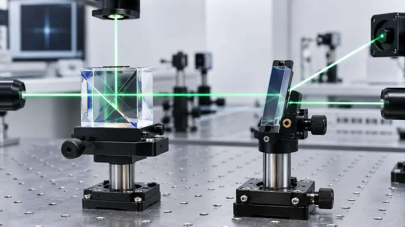
The main difference is not the splitting function — it is the optical geometry
Both designs use a partially reflective optical interface to divide incident optical power between reflected and transmitted paths. A nominal 50:50 beamsplitter, for example, is designed so that reflection and transmission approach the specified ratio under defined operating conditions.
The mechanical form changes how the beam reaches that interface.
Cube beamsplitter
A cube beamsplitter is commonly made from two right-angle prisms assembled around an internal diagonal beamsplitting surface. The input beam normally enters approximately perpendicular to one external face, reaches the internal coating and separates into transmitted and reflected paths.
This geometry is convenient because the external faces can provide clear mechanical references and the reflected beam can be redirected by approximately 90 degrees without tilting an exposed plate in the optical path.
The trade-off is optical path length. The light travels through significantly more substrate than it would in a thin plate. Substrate dispersion, thermal behavior, assembly construction and wavefront requirements can therefore become important.
Plate beamsplitter
A plate beamsplitter uses a flat substrate with the beamsplitting coating typically applied to the front surface. The plate is normally operated at an oblique angle so that the reflected path is separated from the transmitted path.
The structure is mechanically simpler, but the transmitted beam enters and exits a tilted substrate. Refraction therefore shifts the beam laterally even when the two surfaces are parallel and the emerging ray remains parallel to the original direction.
For a plane-parallel plate, the lateral displacement increases with substrate thickness and depends on incidence angle and refractive index. This effect may be negligible in one optical layout and unacceptable in another.
Cube vs plate beamsplitter: engineering comparison
| Design factor | Cube beamsplitter | Plate beamsplitter |
|---|---|---|
| Basic construction | Two prism elements with a beamsplitting interface inside the assembly | Planar substrate with a beamsplitting coating on one surface |
| Transmitted beam displacement | Usually minimized in the standard normal-entry geometry | Parallel plates produce lateral displacement at oblique incidence |
| Optical path in glass | Relatively long | Usually shorter |
| Rear-surface ghost reflection | No plate-style separated rear-surface ghost at the splitting interface, although other surface reflections still require control | Rear surface can produce a secondary reflection unless controlled by AR coating, wedge or optical layout |
| Mechanical integration | Compact reference geometry can simplify mounting and alignment | Requires angular mounting and control of plate orientation |
| Large clear aperture | Increasing cube size also increases prism volume and mass | Plate construction can be attractive where a relatively large aperture and lower mass are required |
| Wavefront considerations | Prism quality, assembly, coating interface and optical path through the substrate all matter | Flatness, thickness, wedge, mounting stress and coating stress can affect transmitted or reflected wavefront |
| Polarization | Depends on coating design, wavelength, incidence geometry and specified s/p behavior | Also depends strongly on coating design, wavelength, AOI and polarization |
| High-power or pulsed use | Substrate, coating and assembly method must be evaluated for the actual optical regime | Lower bulk glass path and absence of a cemented interface can be useful in some designs, but coating and substrate limits still govern performance |
Ghost reflections are one of the most important plate-beamsplitter issues
The intended splitting event occurs at the coated surface. A plate, however, has another optical surface behind it. Any residual reflection from that rear surface can travel along a slightly different path and appear as a weak secondary beam or ghost image.
An anti-reflection coating on the rear surface reduces the unwanted reflected power, but it does not make the interface physically disappear. In applications that are highly sensitive to stray light, a small substrate wedge may be introduced so that the residual reflection leaves at a different angle and can be spatially separated from the useful beam.
A wedge solves one problem while creating another design variable. The transmitted beam is no longer simply translated parallel to the incident beam; the wedge can introduce angular deviation, and that deviation can vary with wavelength because of dispersion.
A cube reduces beam-offset problems, but adds more glass
In a conventional cube layout, the incoming beam enters an external face close to normal incidence. The transmitted path can therefore pass through the cube without the lateral displacement associated with a tilted parallel plate.
This is valuable when the transmitted beam must remain on a fixed mechanical axis or when the designer wants to avoid compensating for an offset elsewhere in the instrument.
The penalty is the amount of material in the beam path. For a broadband source, wavelength-dependent refractive index can introduce additional chromatic optical path effects. For short optical pulses, the material can contribute dispersion. Thermal gradients may also become relevant when absorbed optical power is significant.
The assembly method matters as well. Some cubes use optical adhesive, while other designs can use different joining methods. A specification for UV, high-power, pulsed or temperature-sensitive service should therefore address the complete cube construction rather than assuming that all cubes behave the same way.
Do cube beamsplitters have better polarization performance?
Not automatically.
Polarization behavior comes primarily from the optical coating and incidence conditions, not from the words “cube” or “plate.” At oblique incidence, s- and p-polarized components interact differently with an optical interface. A coating can be designed to reduce the difference, but the acceptable splitting-ratio error has to be defined across the required wavelength range and AOI.
A non-polarizing beamsplitter should therefore be specified by measurable s/p performance under the intended operating conditions. The mechanical architecture alone cannot establish whether a component is sufficiently non-polarizing for an imaging, measurement or interferometric system.
Systems that depend on polarization state may also need to consider phase as well as amplitude. Similar reflected and transmitted power ratios for s and p components do not necessarily mean that the polarization state remains unchanged.
Wavefront quality may matter more than the nominal 50:50 ratio
For simple illumination splitting, small wavefront errors may have little practical effect. Imaging, interferometry and precision metrology can be much less forgiving.
A plate may require control of substrate flatness, parallelism or wedge, coating stress and mounting stress. A cube introduces prism surfaces, an internal interface and a longer path through optical material. The relevant specification is therefore not merely surface quality but the optical performance that the complete component must maintain in the transmitted and reflected paths.
Placement within the optical system also matters. A tilted plate inserted into a converging beam can introduce aberrations. A thick cube in a converging or broadband beam can also alter optical performance. Where possible, beamsplitters are easier to manage in a collimated portion of the beam, but the final decision must follow the actual optical design.
When does a plate beamsplitter make more sense?
A plate is often worth evaluating when the system benefits from a relatively thin optical element, low mass, a larger aperture or a shorter bulk-glass optical path.
It can also be useful in laser layouts where a weak reflected monitoring beam or another controlled split is required and the designer can deliberately route the transmitted offset and any residual ghost away from sensitive detectors.
The choice becomes less attractive when the system cannot tolerate beam displacement, angular deviation from a wedged plate or residual rear-surface reflections.
When does a cube beamsplitter make more sense?
A cube is often attractive when compact mechanical integration, a stable 90-degree beam-routing geometry and minimal transmitted-beam offset are important.
These characteristics can simplify packaging in imaging instruments, machine-vision assemblies and other systems where beam positions must remain closely tied to mechanical references.
A cube is not automatically the better option when weight, aperture, broadband dispersion, ultrashort pulses, thermal loading or the amount of optical material in the beam path becomes the dominant constraint.
How to choose between cube and plate beamsplitters
- Define the optical function. Establish whether the component is splitting illumination, creating a measurement channel, routing an imaging path, monitoring a laser or forming part of an interferometer.
- Fix wavelength and spectral range. A splitting ratio is meaningful only under defined spectral conditions.
- Define AOI and beam geometry. Include the nominal incidence angle and any angular cone or alignment variation that the optic will experience.
- State polarization conditions. Specify unpolarized, random, linear or other relevant polarization requirements and whether s/p ratio differences matter.
- Check beam offset and ghost tolerance. Decide whether the system can accommodate the plate’s transmitted displacement or residual secondary reflection.
- Define aperture and mechanical envelope. Compare clear aperture, thickness, mass and available mounting volume.
- Add wavefront and surface requirements. Imaging and interferometry may require controls that are unnecessary in a simple illumination splitter.
- Describe optical power and pulse conditions. For laser use, include wavelength, beam diameter, power or pulse parameters needed for coating and substrate evaluation.
- Define inspection criteria before production. The drawing and optical specification should state how splitting ratio, dimensions, surface condition and other critical characteristics will be accepted.
Common specification mistakes
Specifying only “50:50”
The same coating does not necessarily produce an identical 50:50 ratio at every wavelength, AOI and polarization state. State the conditions and allowable tolerance.
Ignoring the rear surface of a plate
The secondary surface can matter even when the beamsplitting coating itself performs correctly. AR treatment, wedge and ghost-beam routing belong in the system discussion.
Assuming non-polarizing means polarization-independent
Non-polarizing designs reduce specified s/p differences within defined conditions. They do not remove every amplitude or phase effect associated with polarization.
Choosing a cube only because alignment looks easier
Mechanical convenience should be weighed against optical path length, material dispersion, aperture, mass and the assembly method.
Choosing a plate only because it contains less glass
A thin plate can still cause beam offset, ghost reflections, wavefront error or angular deviation if wedge is introduced. The complete optical path must be evaluated.
Selection should start with the optical system, not the component shape
The cube-versus-plate decision is ultimately a system decision. A compact instrument may benefit from the mechanical reference geometry of a cube. A large-aperture or low-mass system may favor a plate. A laser setup may prioritize ghost control and optical material path, while an imaging system may care more about wavefront quality and beam registration.
The useful specification therefore includes more than a cube or plate designation. Wavelength, splitting ratio, AOI, polarization, clear aperture, substrate, wedge or parallelism, coating requirements, transmitted and reflected wavefront expectations, optical power conditions and inspection criteria should be considered together.
Custom Beamsplitter Requirements
For a custom cube or plate beamsplitter, provide the available drawing or sample together with the operating wavelength, required splitting ratio, angle of incidence, polarization conditions, substrate or material preference, clear aperture, mechanical dimensions, wavefront or flatness requirements, laser conditions where relevant, quantity and inspection criteria.
This information makes it possible to evaluate the beamsplitter as part of the optical system rather than selecting a coating or mechanical form in isolation.
FAQ
1. Is a cube beamsplitter better than a plate beamsplitter?
No. A cube is often easier to integrate mechanically and can minimize transmitted-beam displacement in the standard geometry. A plate generally uses less optical material and can be attractive for larger apertures or lower-mass systems. The correct choice depends on the complete optical layout.
2. Why does a plate beamsplitter shift the transmitted beam?
The beam refracts as it enters an angled substrate and refracts again when it exits. With parallel surfaces, the emerging beam is usually parallel to the original beam but laterally displaced. The amount of displacement depends on plate thickness, AOI and refractive index.
3. How can ghost reflections from a plate beamsplitter be reduced?
A rear-surface AR coating can reduce the unwanted reflection. A substrate wedge can also direct the residual ghost away from the main beam. The wedge angle should be selected from the actual system geometry because it can also introduce transmitted-beam deviation.
4. Are cube beamsplitters free from ghost reflections?
Not completely. The cube architecture removes the characteristic separated rear-surface ghost of a parallel plate at the splitting interface, but reflections from external surfaces, coating interfaces or other elements can still create stray light or optical feedback.
5. Which type is better for laser systems?
That depends on laser wavelength, beam size, CW or pulsed operation, pulse duration, power density, coating design, substrate and assembly construction. Plate designs can reduce the amount of bulk glass in the beam path, while cubes may offer useful alignment advantages. Laser suitability should be specified rather than inferred from the component shape.
6. Which type is better for imaging?
Cube geometry can simplify beam registration and packaging, while plate designs can reduce bulk optical material. For precision imaging, transmitted and reflected wavefront, ghosting, aberrations, aperture and placement in converging or collimated light are usually more important than choosing a cube or plate by name.
7. What information should be included in a custom beamsplitter specification?
Include wavelength or spectral range, splitting ratio and tolerance, AOI, polarization, clear aperture, substrate, dimensions, surface and wavefront requirements, coating surfaces, wedge or parallelism where relevant, optical power or pulse conditions, environmental requirements and inspection criteria.