
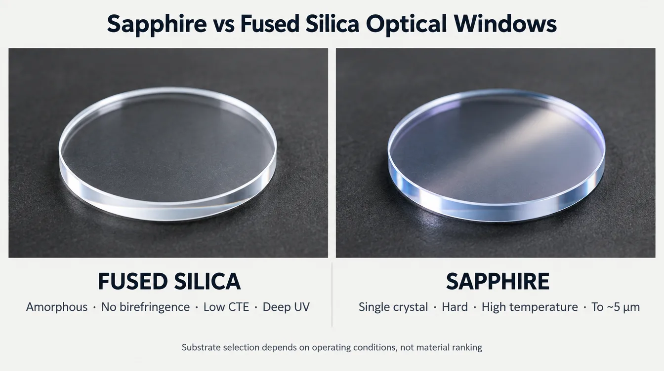
Choose fused silica when the window must work in the deep UV, must not disturb polarization or wavefront, or must survive fast thermal transients; choose sapphire when the window faces abrasion, high pressure, chemical attack or high temperature, or when the band extends past roughly 2.5 µm into the mid-wave infrared. Both materials are used as optical windows in the same instruments, and the decision is rarely about optical quality alone — it is about which failure mode the window is expected to survive.
What is the actual difference between a sapphire window and a fused silica window?
Fused silica is an amorphous, high-purity SiO₂ glass. It has no crystal structure, no preferred axis and no intrinsic birefringence. Its optical homogeneity is controlled by the melting or deposition process, and its behavior is isotropic in every direction, which is why it dominates interferometry, laser optics and UV instrumentation.
Sapphire is single-crystal aluminium oxide (Al₂O₃), grown by Kyropoulos, EFG, HEM or similar methods and then cut to a defined crystal orientation. It is hexagonal and uniaxial: the refractive index differs along and across the optic axis. That crystal structure is the source of both its mechanical advantage and its optical complications.
Everything else in this comparison follows from that one structural difference — glass versus crystal.
Which substrate covers your wavelength band?
Fused silica: the UV grade and IR grade are not interchangeable
Commercial fused silica is supplied in two broad families that behave very differently at the band edges:
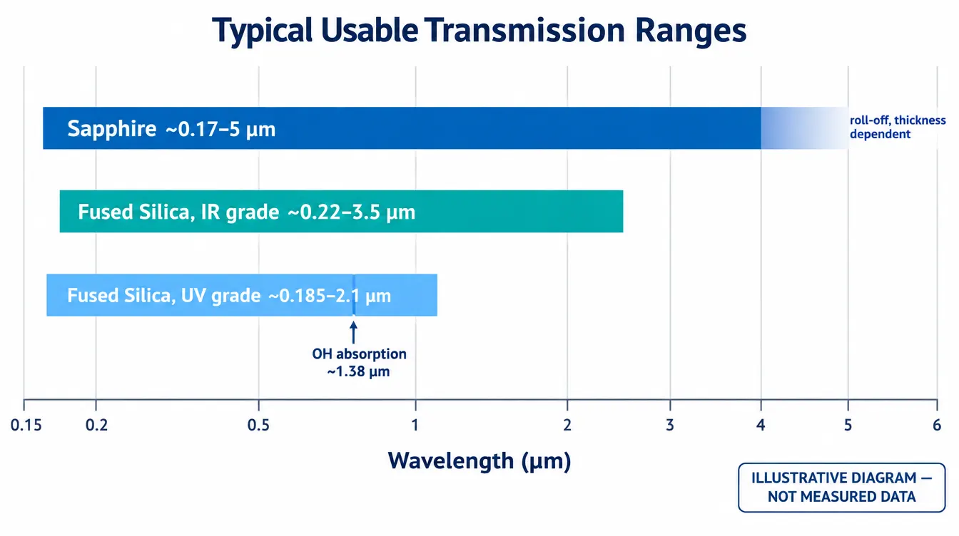
- UV grade (high OH content) — usable transmission from roughly 185 nm into the near infrared, with a hydroxyl absorption feature near 1.38 µm and strong absorption approaching 2.7 µm.
- IR grade (low OH content) — suppressed OH absorption, extending usable transmission to roughly 3.5 µm, but with a noticeably poorer deep-UV edge.
Specifying “fused silica” without naming the grade is one of the most common sources of a window that passes incoming inspection and still fails in the application. If your band touches either edge, the grade belongs on the drawing.
Sapphire: broad coverage, with a real limit in the MWIR
Sapphire transmits from roughly 150–170 nm to about 5 µm, so a single substrate can cover UV, visible, SWIR and part of the mid-wave infrared. Transmission falls off progressively beyond about 4.5 µm, and the usable upper limit depends strongly on thickness — a 1 mm window and a 6 mm pressure window do not have the same effective cut-off. For bands beyond 5 µm, sapphire is the wrong material and the discussion moves to silicon, germanium or ZnSe, which is covered separately under optical materials and infrared optics.
How do the key material properties compare?
Typical room-temperature values for standard commercial grades are shown below. They are material references for first-pass selection, not acceptance criteria: sapphire values vary with crystal orientation, and fused silica values vary with grade and manufacturing route. Confirm against the material datasheet of the grade actually being purchased.
| Property | Fused Silica | Sapphire (Al₂O₃) | Engineering consequence |
|---|---|---|---|
| Structure | Amorphous glass | Single crystal, uniaxial | Isotropy vs. orientation-dependent behavior |
| Usable transmission | ~185 nm–2.1 µm (UV grade); to ~3.5 µm (IR grade) | ~0.17–5 µm, thickness dependent | Sapphire covers MWIR; silica covers deep UV |
| Refractive index (≈588 nm) | ≈1.458 | ≈1.768 / 1.760 (no / ne) | Higher Fresnel loss on sapphire |
| Uncoated transmission, two surfaces (VIS) | ≈93% | ≈86% | AR coating is close to mandatory on sapphire |
| Birefringence | None intrinsic | Δn ≈ 0.008, uniaxial | Polarization and retardance effects |
| Knoop hardness | ≈500–600 kg/mm² | ≈1800–2200 kg/mm², orientation dependent | Abrasion and particulate resistance |
| Young’s modulus | ≈73 GPa | ≈345–400 GPa | Deflection under pressure load |
| Density | 2.20 g/cm³ | 3.98 g/cm³ | Mass penalty on large apertures |
| CTE (near RT) | ≈0.55 × 10⁻⁶/K | ≈4.5–5.3 × 10⁻⁶/K, axis dependent | Mounting stress and thermal transients |
| Thermal conductivity (RT) | ≈1.4 W/m·K | ≈25–35 W/m·K, axis and temperature dependent | Heat removal from the window |
| Typical continuous service temperature | ≈900 °C | ≈1600 °C and above in suitable atmospheres | Furnace, combustion and process viewports |
| Chemical behavior | Excellent, but attacked by HF and hot alkali | Inert to most acids and alkalis at RT; attacked by molten alkali at high temperature | Process and cleaning compatibility |
| Relative fabrication effort | Low | High — diamond processing throughout | Cost, lead time, achievable geometry |
When does sapphire’s hardness actually earn its cost?
Sapphire is roughly three to four times harder than fused silica on the Knoop scale and several times stiffer. That matters in a specific set of conditions:
- Particulate and abrasive flow — sand, slurry, dust, blast media, machining swarf. A fused silica window scratches and its scatter rises until the measurement degrades; sapphire holds its surface far longer.
- Pressure containment — the higher modulus and flexural strength allow a thinner window for the same differential pressure and clear aperture, which partly offsets the material cost and reduces optical path length in the medium.
- Aggressive cleaning cycles — windows wiped daily in production equipment accumulate cleaning damage on softer substrates.
- Chemical exposure — sapphire tolerates acids and solvents that will etch or haze glass over time.
Where the environment is clean and controlled — a sealed enclosure, a laboratory instrument, a laser cavity output — hardness buys nothing. In those systems the sapphire premium purchases a property the application never uses, while importing birefringence, higher Fresnel loss and a harder fabrication problem. Hardness is not a general quality ranking; it is a resistance to one specific class of damage.
Does sapphire birefringence affect your measurement?
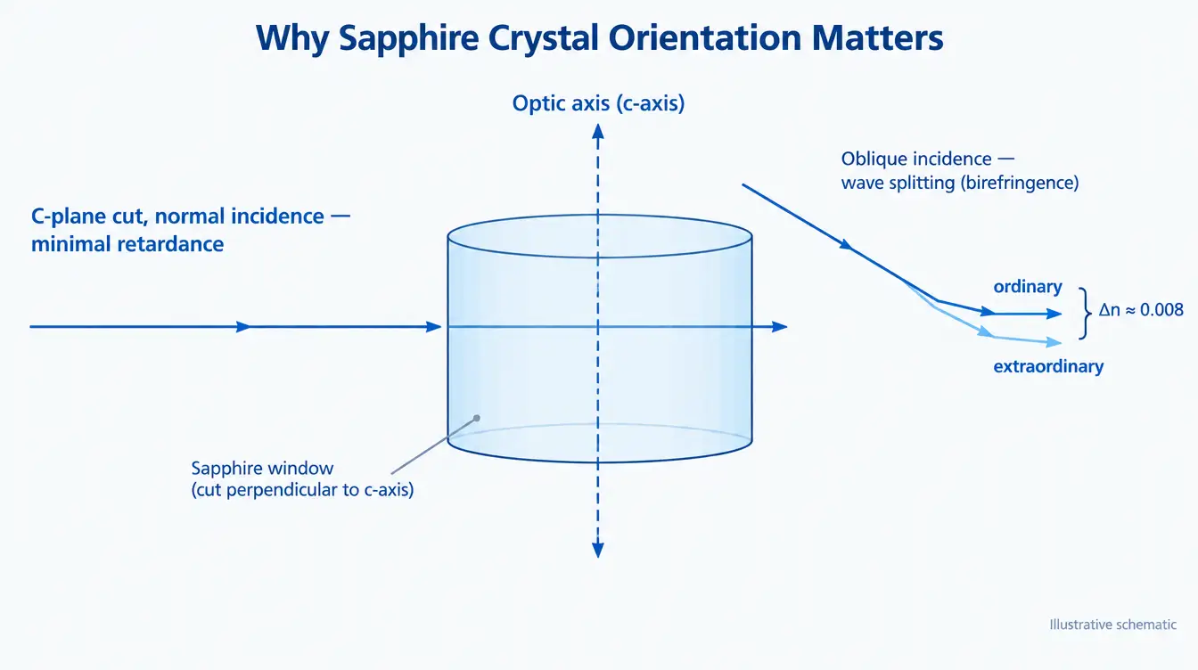
Because sapphire is uniaxial, a ray passing through it generally splits into ordinary and extraordinary components with a small index difference. The practical impact depends on the crystal orientation supplied and on how the window is used:
- C-plane (0001) cut — the optic axis is normal to the surface, so light at normal incidence sees essentially no retardance. This is the default choice for imaging and polarization-sensitive windows.
- Random or A-plane cut — cheaper and common for protective windows, but it introduces retardance and can produce double-image or contrast effects in imaging paths.
- Off-normal rays — even a C-cut window shows increasing retardance with angle, so a fast converging beam or a wide field of view is not fully protected by the orientation choice alone.
If the system uses polarimetry, ellipsometry, interferometry, polarized machine vision or a polarization-multiplexed sensor, and the requirement is tight, fused silica removes the variable entirely. If sapphire is required for environmental reasons, the crystal orientation must be an explicit line on the drawing — not left to the supplier’s standard.
Which substrate handles your thermal environment better?
This is the clearest trade-off in the comparison, and it splits in two directions.
Sapphire wins on absolute temperature and heat removal. Its continuous service temperature is far above fused silica’s, and its thermal conductivity is more than an order of magnitude higher, so absorbed energy is conducted to the mount instead of building a thermal gradient in the aperture. Furnace viewports, combustion diagnostics and high-temperature process windows are natural sapphire applications.
Fused silica wins on thermal transients and dimensional stability. Its expansion coefficient is roughly an order of magnitude lower, so a rapid temperature change produces far less internal stress and far less mount-induced distortion. Fused silica tolerates steep temperature shock that would crack many crystalline materials, and its low CTE is why it is the reference substrate for dimensionally critical and interferometric optics. Both materials also shift focus slightly with temperature through dn/dT, which matters in precision imaging paths held over a wide temperature range.
Stated as a selection rule: high steady temperature and heat flux point to sapphire; fast cycling, thermal shock and dimensional stability point to fused silica. A window that sits at 800 °C and one that swings 400 °C in seconds are different problems with different answers.
What does each material cost you in fabrication and geometry?
Material price is only part of the difference. Sapphire’s hardness that protects it in service also resists every step that shapes it: coring, grinding, lapping, polishing and edging all run on diamond, more slowly, with more tool wear and a higher risk of edge chipping on thin parts. The practical consequences are longer lead times, higher cost at tight figure and surface-quality specifications, and limits on very thin or very large geometries that fused silica reaches more easily. Fused silica polishes readily to demanding surface figure and surface quality, and is available in large blanks, which is why large-aperture and high-precision windows gravitate toward it whenever the environment permits.
Coating behaves differently on the two substrates as well. Sapphire’s higher index needs a different AR design than fused silica to reach the same residual reflectance, and on a hard substrate the coating often becomes the durability-limiting layer — an abrasion-resistant window with a soft coating is not an abrasion-resistant window. Coating specification, adhesion and environmental durability requirements should be reviewed together with the substrate rather than added afterwards; GIAI evaluates substrate, geometry, coating and inspection requirements together during optical manufacturing review before the process route is fixed.
How should the window be specified, and what goes wrong most often?
A workable selection sequence for a window is: define the wavelength range and required transmission first, then the environment (temperature, pressure, chemicals, abrasion), then the optical quality the system actually needs, and only then the material. Choosing the substrate first and fitting the requirements to it afterwards is where most specification problems begin.
Recurring mistakes seen on window drawings:
- Naming a material without a grade or orientation. “Fused silica” hides a 1.5 µm difference at the IR edge; “sapphire” hides the birefringence behavior.
- Specifying transmission without a wavelength and a condition. A transmission number is meaningless without the band, the incidence angle and whether it refers to coated or uncoated parts.
- Copying a surface quality and figure spec from an unrelated drawing. Tight figure on sapphire is expensive; tight figure on a protective viewport that never forms an image is wasted money.
- Ignoring parallelism on a window in a collimated or imaging path. Wedge deviates the beam and, in an imaging system, introduces aberration that no coating will fix.
- Assuming hardness means durability. Sapphire with an unsuitable coating can fail sooner in service than coated fused silica.
- Leaving acceptance criteria undefined. Measurement method, condition and pass/fail limits belong on the drawing; the inspection and acceptance approach should be agreed before production, not disputed after delivery.
For bands extending beyond sapphire’s limit, the comparison shifts entirely to infrared optical materials, where transmission, absorption and thermal behavior are evaluated against the same framework.
FAQ
Is sapphire always better than fused silica for optical windows?
No. Sapphire is harder, more chemically resistant and usable at higher temperature and further into the infrared, but it is birefringent, heavier, more reflective when uncoated and significantly more expensive to fabricate to tight optical tolerances. In a clean, controlled environment, fused silica usually delivers equal or better optical performance at lower cost.
Which material transmits further into the infrared?
Sapphire, to approximately 5 µm with a thickness-dependent roll-off beyond about 4.5 µm. IR-grade fused silica reaches roughly 3.5 µm; UV-grade fused silica is effectively limited below about 2.1 µm by hydroxyl absorption.
Do I need an AR coating on a sapphire window?
In most cases, yes. Sapphire’s index near 1.77 gives about 7.7% reflection per uncoated surface in the visible, or roughly 14% total loss, compared with about 7% for fused silica. Where transmitted signal, stray light or back-reflection matters, an AR coating designed for sapphire’s index and the working angle of incidence is required.
What crystal orientation should a sapphire window be?
C-plane (0001) for imaging, polarization-sensitive and measurement paths, because the optic axis is normal to the surface and retardance at normal incidence is minimal. Random or A-plane cuts are acceptable for purely protective windows where polarization and image quality are not evaluated. The orientation should be stated explicitly on the drawing.
Which material handles thermal shock better?
Fused silica, because its expansion coefficient is roughly ten times lower, so rapid temperature changes generate much smaller internal stresses. Sapphire is the better choice for high steady-state temperature and for conducting absorbed heat away, but not automatically for fast thermal cycling.
Can both materials be supplied to the same tolerances?
Not at the same cost or lead time. Tight surface figure, tight parallelism and high surface quality are achievable on both, but sapphire requires diamond processing throughout and the effort rises steeply as tolerances tighten, particularly on thin parts and large apertures. Achievable limits should be confirmed against the specific drawing rather than assumed from a general specification.
Specifying a window for review
Window selection is decided by the operating conditions, not by a material ranking. For a technical evaluation, send the drawing, optical specification or sample together with the wavelength range and required transmission, the substrate or candidate materials, dimensions including thickness, clear aperture and parallelism, coating requirements and the angle of incidence, the operating environment (temperature, pressure, chemical and abrasion exposure), inspection criteria and measurement conditions, and the expected quantity. With those parameters defined, material and process feasibility can be assessed against the actual part — submit the specification for technical review.