
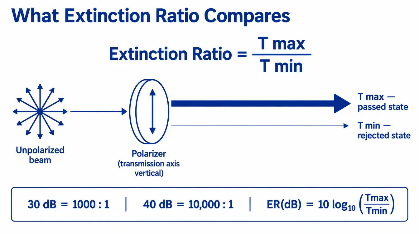
Extinction ratio is the ratio between the transmittance a polarizer gives to the polarization state it passes and the transmittance it gives to the orthogonal state it is meant to block, at a stated wavelength, angle of incidence and aperture. A part specified at 1000:1 transmits a thousand times more of the intended state than of the rejected state under the exact conditions written on the datasheet. It does not automatically hold at a different wavelength, in a converging beam, or after the element has been clamped into a mount.
What does the ratio actually compare?
For a polarizer illuminated by fully polarized light, rotate the input polarization and record the maximum and minimum transmitted power. The extinction ratio is:
ER = Tmax / Tmin, usually written as Tp/Ts for a transmitted beam.
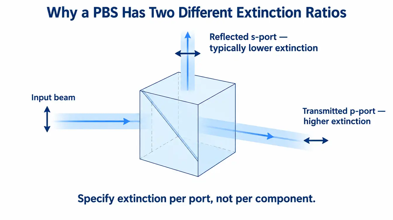
Two properties follow directly from that definition. First, extinction ratio is a ratio of two transmittances, so it says nothing on its own about how much light survives: a polarizer with Tp = 0.45 and one with Tp = 0.92 can carry the same ER number. Transmission and extinction must be specified together. Second, ER is defined per beam and per condition. A polarizing beamsplitter has one extinction ratio for the transmitted port and a different, usually much lower one for the reflected port.
The same physical behaviour is sometimes reported as degree of polarization:
DOP = (Tmax − Tmin) / (Tmax + Tmin) = (ER − 1) / (ER + 1)
DOP compresses badly at high performance — 1000:1 and 10 000:1 both round to 99.9 % and above — which is why polarization-critical specifications are written as ratios or in decibels rather than as a percentage.
Is 30 dB the same thing as 1000:1?
Usually yes, but the convention has to be confirmed rather than assumed. When extinction ratio is quoted in decibels for optical power, the standard conversion is:
ER(dB) = 10 · log10(Tmax/Tmin)
So 20 dB is 100:1, 30 dB is 1000:1, 40 dB is 10 000:1, and 50 dB is 100 000:1. Some documents, particularly those originating in fibre optics or in amplitude-based measurements, use 20 · log10, which turns the same physical part into twice the decibel figure. A “40 dB polarizer” is therefore ambiguous until the convention is stated. On a purchase specification, write the linear ratio as well as the decibel value, or define the logarithm explicitly. This single ambiguity is a common source of incoming-inspection disputes, and it costs nothing to remove.
Why does a crossed pair give a different number than a single element?
Many datasheets and most workshop measurements use two identical polarizers, comparing transmitted power with the axes parallel and crossed. With unpolarized input and the usual notation where k1 is the principal transmittance and k2 the minor transmittance of one element:
- Parallel: T∥ = ½ (k12 + k22)
- Crossed: T⊥ = k1k2
When k1 is much larger than k2, the measured pair ratio T∥/T⊥ approaches k1/(2k2), which is about half the single-element extinction ratio k1/k2. A factor of two is small next to the three or four orders of magnitude being discussed, but it is large enough to fail a part that was specified at exactly 1000:1 and measured as a pair. The specification should state whether the number refers to a single element under polarized illumination or to a crossed pair under unpolarized illumination.
How much extinction ratio do different polarizer types deliver?
Polarizers separate states by absorption, by reflection at an interface, by a sub-wavelength metal structure, or by birefringent walk-off. Each mechanism sets its own ceiling and its own weakness. The ranges below are the values commonly published across the industry for these technologies; they describe what the mechanisms can do, not a guaranteed figure for any particular part.
| Polarizer type | Typical published ER range | Spectral coverage | Angular acceptance | Principal limitation |
|---|---|---|---|---|
| Absorptive dichroic (sheet or glass) | 103–105:1 | Band-limited by the dichroic medium | Wide | Rejected state is absorbed, so heating limits usable power |
| Wire grid | 102–104:1, generally higher in the infrared | Very broadband | Wide | Rejected beam is reflected and must be dumped; grid surface is fragile |
| Thin-film plate polarizer (Brewster-type) | 102–103:1 transmitted | Design band | Narrow, centred on the design angle | Performance collapses away from the design AOI |
| Polarizing beamsplitter cube | Transmitted port typically 103:1; reflected port often one to two orders lower | Design band | Small, a few degrees | Asymmetric ports; cement limits power handling |
| Birefringent crystal prism (Glan-type) | 105–106:1 | Broad within the crystal’s transmission range | Limited field angle | Aperture, length and cost scale steeply |
The practical reading of this table is that extinction ratio is not an independent variable. Choosing 105:1 selects a technology, and that technology then fixes the acceptance angle, the bandwidth, the power handling and the physical envelope.
What degrades extinction ratio once the part is in a system?
Datasheet conditions are close to ideal: collimated, monochromatic or narrowband light, normal or design incidence, small aperture, room temperature. Real assemblies depart from all of these.
- Wavelength. Extinction is spectrally structured. A polarizer optimised at 633 nm may lose an order of magnitude at 450 nm or at 900 nm. Broadband sources see a weighted average, not the peak value.
- Angle of incidence and cone angle. Interface-based polarizers depend on the angle at the coating. In an f/4 cone the marginal rays arrive several degrees from the design angle, and the integrated extinction is dominated by those rays. This is the usual reason a cube that measured 1000:1 on a collimated bench delivers far less in an imaging path.
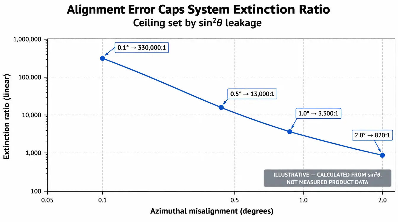
- Azimuthal alignment. Rotational error between two polarization-defining elements leaks light in proportion to sin2θ, which places a hard ceiling on the achievable system extinction regardless of component quality.
- Stress birefringence. Over-constrained mounts, cured adhesive shrinkage and thermal gradients all introduce retardance that converts the passed state back into the rejected one.
- Scatter and surface defects. Scattered light is largely depolarized and lands in the Tmin channel. On high-extinction parts, surface quality and cleanliness become extinction specifications in practice.
| Azimuthal misalignment | Leakage, sin2θ | Highest system ER obtainable |
|---|---|---|
| 0.1° | 3.0 × 10⁻⁶ | ≈ 330 000:1 |
| 0.5° | 7.6 × 10⁻⁵ | ≈ 13 000:1 |
| 1.0° | 3.0 × 10⁻⁴ | ≈ 3 300:1 |
| 2.0° | 1.2 × 10⁻³ | ≈ 820:1 |
A 105:1 polarizer in a mount with one degree of rotational uncertainty is a 3 300:1 system. Alignment tolerance, not component grade, is often the limiting term.
How is extinction ratio measured, and what belongs on the report?
The measurement is conceptually simple and experimentally demanding, because Tmin is a very small signal sitting on top of stray light and detector noise.
- The reference polarizer used as analyser must have substantially better extinction than the part being measured, or the setup measures itself.
- The detector chain must be linear across the full dynamic range, and background and stray light must be subtracted rather than ignored.
- Beam geometry must be controlled: aperture, degree of collimation and incidence angle all change the result.
- For a beamsplitter, transmitted and reflected ports are reported separately.
A usable acceptance record therefore states wavelength or spectral band, source bandwidth, angle of incidence, beam diameter and convergence, clear aperture, temperature, whether the value is single-element or crossed-pair, and the decibel convention. An extinction ratio reported without those conditions cannot be reproduced and should not be used as an acceptance criterion.
What is given up to obtain a higher extinction ratio?
Higher extinction is never free, and the cost is paid in a different column of the specification each time.
- Transmission. Pushing the rejected state down generally trims the passed state as well, through added absorption, additional layers or a longer optical path.
- Bandwidth. Interference-based designs buy extinction by narrowing the band over which the design angle and layer stack work.
- Acceptance angle. The highest-extinction technologies are also the most angle-sensitive, which conflicts directly with fast optics and wide fields.
- Power handling. Absorptive polarizers convert the rejected beam into heat; cemented assemblies concentrate damage risk at the bond line. High extinction and high average power tend to pull toward different solutions.
- Size, mass and cost. Crystal prisms scale in all three at once as aperture grows.
- Wavefront and path length. Thicker elements add optical path, wavefront error and beam displacement that the surrounding design has to absorb.
How much extinction ratio does the application actually require?
Work backwards from the measurement or the failure mode rather than from the largest available number.
- Glare and reflection suppression in machine vision is a contrast problem. Two orders of magnitude are typically enough, and acceptance angle and uniformity across the field matter more than the last factor of ten in extinction.
- Display, projection and modulator contrast is set by the whole polarization chain, including retardance in every element between the polarizer and the analyser.
- Laser isolation, polarimetry and ellipsometry genuinely need 104:1 and above, and the mount, the alignment resolution and the stray-light control must be specified at the same level.
- Signal-to-background calculations give the honest answer: if a residual 1 % polarization leak still sits below the detector noise floor, specifying 105:1 buys nothing and constrains every other parameter.
Which specification mistakes cause acceptance disputes?
- Quoting a crossed-pair number and testing against a single-element definition, or the reverse.
- Applying a transmitted-port extinction ratio to the reflected port of a beamsplitter.
- Assuming a peak-wavelength value applies across a broadband source.
- Specifying extinction in a collimated condition and using the part in a converging beam.
- Leaving the decibel convention undefined.
- Specifying component extinction far above what the mount’s rotational tolerance can preserve.
- Treating extinction ratio as a single number rather than as a value tied to wavelength, angle and aperture.
FAQ
Is extinction ratio the same as contrast ratio?
They are related but not interchangeable. Extinction ratio is a property of a component measured under stated conditions; contrast ratio usually describes the output of a complete system, including retardance, scatter and stray light contributed by every element in the path.
Can a polarizer’s extinction ratio exceed the source polarization purity?
Not in the measurement. If the analyser or the reference polarizer has lower extinction than the part under test, the result reflects the setup rather than the part. The reference must be comfortably better than the specification being verified.
Does extinction ratio change with temperature?
It can, through thermally induced stress birefringence, mount deformation and, in absorptive designs, heating of the medium itself. Where a system runs over a wide temperature range, extinction should be verified at the operating extremes rather than only at ambient.
Why does a polarizing beamsplitter perform so differently on its two ports?
The multilayer interface is designed to transmit the p-state efficiently while reflecting the s-state. The transmitted beam is cleaned by the stack; the reflected beam collects residual p-light directly, so the reflected port is normally the weaker of the two. Where both outputs must be pure, a clean-up polarizer is placed in the reflected arm.
Which parameters should a polarizer drawing carry alongside extinction ratio?
Wavelength or band, principal transmittance, angle of incidence and acceptance cone, clear aperture and outer dimensions, substrate or polarizer type, surface quality, wavefront requirement, axis orientation tolerance relative to a datum, damage threshold where a laser is involved, and the test conditions under which extinction will be accepted.
Specifying a polarization-sensitive component for manufacture
Extinction ratio only becomes a manufacturable requirement once it is bound to conditions. For a technical review of a polarization-sensitive assembly, send the operating wavelength or spectral band, the required extinction ratio with its definition and decibel convention, the transmission requirement, angle of incidence and beam convergence, substrate or material preference, clear aperture and outer dimensions, coating requirements on the remaining surfaces, axis orientation tolerance and datum, surface quality and wavefront criteria, inspection and acceptance method, and expected quantity. With a drawing, specification or sample and those parameters, GIAI Photonics can assess manufacturing feasibility and the inspection method against the acceptance criteria you intend to apply.