
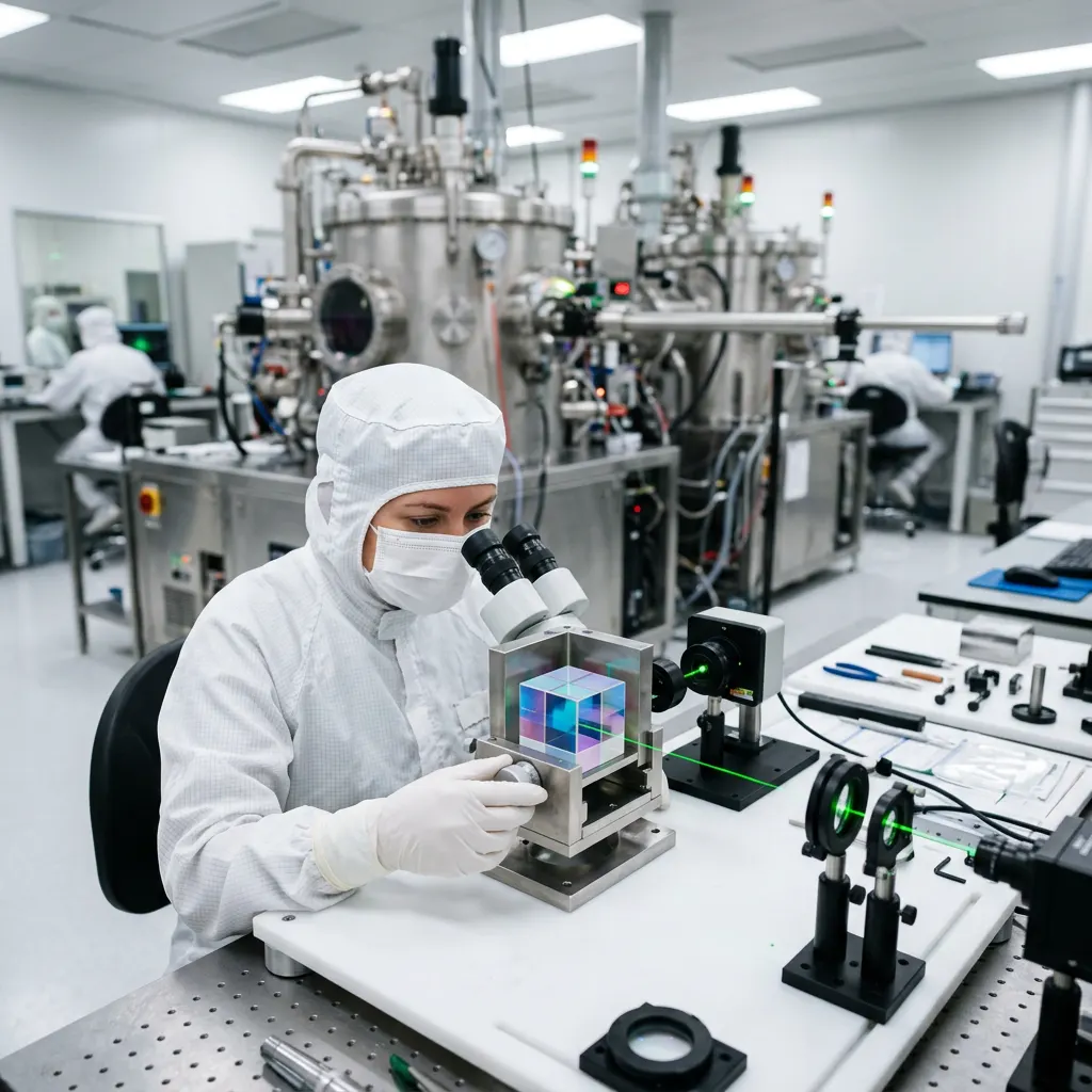
For optical designers, machine vision integrators, and laser systems engineers, standard off-the-shelf optical components often fall short of strict system requirements. Whether the limitation is an unconventional form factor, a specific narrow bandpass requirement, or extreme environmental survivability, transitioning from standard catalog items to custom-engineered solutions is a critical step in product development.
Working with a custom precision optics manufacturer requires a deep understanding of optical parameters, fabrication tolerances, thin-film coating technologies, and metrology. This guide details the technical considerations involved in specifying, manufacturing, and validating custom optical components, from lenses and prisms to highly specialized interference filters.
1. Defining “Precision” in Optical Manufacturing
The term “precision” in optics is not subjective; it is quantified through a specific set of standardized parameters. A reliable custom precision optics manufacturer controls these variables tightly through deterministic fabrication and metrology.
Surface Accuracy and Wavefront Error
Surface accuracy (or surface figure) measures the deviation of an optical surface from its ideal theoretical shape (e.g., a perfect plane or a perfect sphere). It is typically expressed in fractions of a reference wavelength, usually Helium-Neon (HeNe) at 632.8 nm. For high-precision applications such as laser interferometry or high-resolution imaging, a surface flatness of λ/10 or even λ/20 may be required.
Transmitted Wavefront Error (TWE) evaluates how the entire component—including both surfaces and the bulk material—distorts the phase of a transmitted wavefront. A component with excellent surface flatness can still exhibit poor TWE if the substrate material has high internal stress or refractive index inhomogeneity.
Surface Quality (Scratch-Dig)
Surface quality specifies the allowable cosmetic defects on an optical surface, which can scatter light and create stray light in a system. The most common standard is the MIL-PRF-13830B scratch-dig specification.
- Commercial quality: 60-40 to 80-50 (suitable for basic imaging or illumination).
- Precision quality: 40-20 to 20-10 (standard for machine vision, sensing, and low-power lasers).
- High-precision / Laser quality: 10-5 (required for high-power laser optics where surface defects act as localized absorption points, reducing the Laser Induced Damage Threshold, or LIDT).
Parallelism and Total Thickness Variation (TTV)
For windows, filters, and beamsplitters, parallelism dictates the angle between the two optical surfaces. Poor parallelism causes beam deviation (wedge) and astigmatism in transmitted converging beams. Precision optics typically maintain parallelism of less than 10 arcseconds. Total Thickness Variation (TTV) is a related metric often used in semiconductor and sensor manufacturing, measuring the absolute difference between the maximum and minimum thickness of a substrate.
2. The Custom Manufacturing and Fabrication Process
Translating an optical design into a physical component involves multiple deterministic subtractive processes and material sciences.
Substrate Selection and Shaping
The foundation of any optical component is the substrate. The choice of material dictates the transmission range, thermal stability, and mechanical strength. A custom precision optics manufacturer typically works with:
- Visible to Near-Infrared (NIR): N-BK7, B270, Borofloat.
- Ultraviolet (UV) to NIR: UV Fused Silica (excellent thermal stability and high transmission).
- Infrared (IR): Silicon (Si), Germanium (Ge), Zinc Selenide (ZnSe), and Sapphire (Al₂O₃).
Raw glass boules are cored, sliced, and generated into near-net shapes using diamond-tooled CNC machinery. This stage establishes the physical dimensions but leaves a highly scattering, subsurface-damaged finish.
Grinding, Polishing, and Finishing
To achieve an optical finish, the shaped substrate undergoes loose abrasive grinding to remove subsurface damage, followed by pitch or polyurethane polishing using cerium oxide or aluminum oxide slurries.
For ultra-precision components requiring λ/20 flatness, advanced sub-aperture polishing techniques are utilized, such as Magnetorheological Finishing (MRF) or Ion Beam Figuring (IBF). These computer-controlled processes selectively remove material at the nanometer level based on metrology feedback loops.
3. Custom Optical Coatings (Thin-Film Deposition)
Bare glass reflects approximately 4% of incident light per surface (for N-BK7). To control the transmission, reflection, and absorption of specific wavelengths, multiple layers of dielectric materials are deposited onto the polished substrate. The coating process is arguably the most complex capability of a custom precision optics manufacturer.
Working Principle of Interference Coatings
Optical coatings rely on thin-film interference. By depositing alternating layers of high-index and low-index materials (such as TiO₂ and SiO₂) at highly controlled thicknesses (typically quarter-wave optical thickness), the reflected light waves from each boundary either constructively or destructively interfere.
Deposition Technologies
The performance, durability, and spectral shift of the filter depend heavily on the deposition method:
- Electron Beam (E-Beam) Evaporation: Traditional method suitable for broad-band anti-reflection (BBAR) and standard mirrors. The films can be porous, leading to moisture absorption and subsequent spectral shift when operating in humid environments.
- Ion-Assisted Deposition (IAD): An ion source compacts the evaporating material onto the substrate. This increases film density, dramatically reducing moisture shift and improving mechanical durability.
- Ion Beam Sputtering (IBS): The highest precision method. High-energy ions sputter target materials onto the substrate. IBS produces fully dense, amorphous, defect-free coatings with extremely low scatter and absorption. This is essential for ultra-narrow bandpass filters and high-LIDT laser mirrors.
Dielectric interference coatings are highly sensitive to the Angle of Incidence. As the AOI increases from 0° (normal incidence), the spectral performance shifts toward shorter wavelengths (blue shift). When specifying custom filters or dichroic mirrors, always explicitly state the nominal AOI and the Cone Angle (numerical aperture) of the incident beam.
4. Metrology: Validating Optical Performance
A custom precision optics manufacturer is only as capable as its metrology department. You cannot manufacture what you cannot measure.
Spectrophotometry (Spectral Performance)
For filters, windows, and lenses, the spectral transmission and reflection are measured using high-resolution spectrophotometers. Key parameters verified include:
- Center Wavelength (CWL) and Full Width at Half Maximum (FWHM): Critical for narrow bandpass filters used in fluorescence and LiDAR.
- Optical Density (OD): Measures the blocking (attenuation) capability of a filter outside its passband. An OD of 4 means 0.01% transmission. High-precision spectrophotometers are required to accurately measure OD6 or higher.
Interferometry (Surface Figure)
Laser interferometers compare the manufactured optical surface against a calibrated reference flat or sphere. The resulting interference pattern (interferogram) is analyzed via software to quantify peak-to-valley (PV) and Root Mean Square (RMS) surface error, ensuring the component meets the required fractional wavelength specification.
5. Specification Guidelines for Engineers
When drafting technical drawings or RFQs for custom optics, precision comes at a cost. Understanding where to tighten tolerances and where to relax them is key to efficient procurement.
Avoiding Over-Specification
Avoid defaulting to extreme tolerances if the system does not require them. For example, specifying a 10-5 scratch-dig surface on an illumination condenser lens dramatically increases manufacturing and inspection costs but provides no measurable improvement in system performance over a 60-40 specification. Reserve 10-5 for focal planes, imaging systems, and high-power laser paths.
Clear Distinction of Parameters
Ensure that parameters are clearly separated. A common error is confusing substrate transmission with coated transmission. A fused silica window transmits well into the UV, but if coated with a standard visible BBAR, the UV transmission will be severely blocked. Specify the exact performance required for the finished, coated component.
Frequently Asked Questions
What is the difference between custom and off-the-shelf optical components?
Off-the-shelf optics are manufactured in high volumes to generalized specifications, making them cost-effective for prototyping. Custom optics are fabricated to exact client specifications, allowing for unique dimensions, bespoke coating curves, non-standard substrate materials, and tightly controlled tolerances (such as TTV or specific wavefront errors) that catalog components cannot provide.
How does a manufacturer measure surface quality (scratch-dig)?
Scratch-dig is typically evaluated visually by trained technicians under specific controlled lighting conditions, comparing the optical surface to a calibrated physical standard (such as the MIL-PRF-13830B standard set). Advanced metrology may use automated machine vision microscopes to map and measure the physical size of defects for highly critical laser applications.
Why do optical filters shift in performance when tilted?
Interference filters rely on the optical path length through alternating thin-film layers. When the Angle of Incidence (AOI) increases, the path length the light travels through the layers changes, altering the phase condition for constructive interference. This always results in the Center Wavelength (CWL) and cut-on/cut-off edges shifting toward shorter (bluer) wavelengths.
What does Optical Density (OD) mean in optical filters?
Optical Density is a logarithmic measurement of light attenuation. It is defined as OD = -log10(T), where T is transmission. Therefore, an OD of 1 equals 10% transmission, OD 2 equals 1%, OD 3 equals 0.1%, and OD 6 equals 0.0001%. It is used to specify how much out-of-band light a filter blocks, which is critical for signal-to-noise ratios in sensors.
