
Technical Resources
Fluorescence Filter Set Design Basics
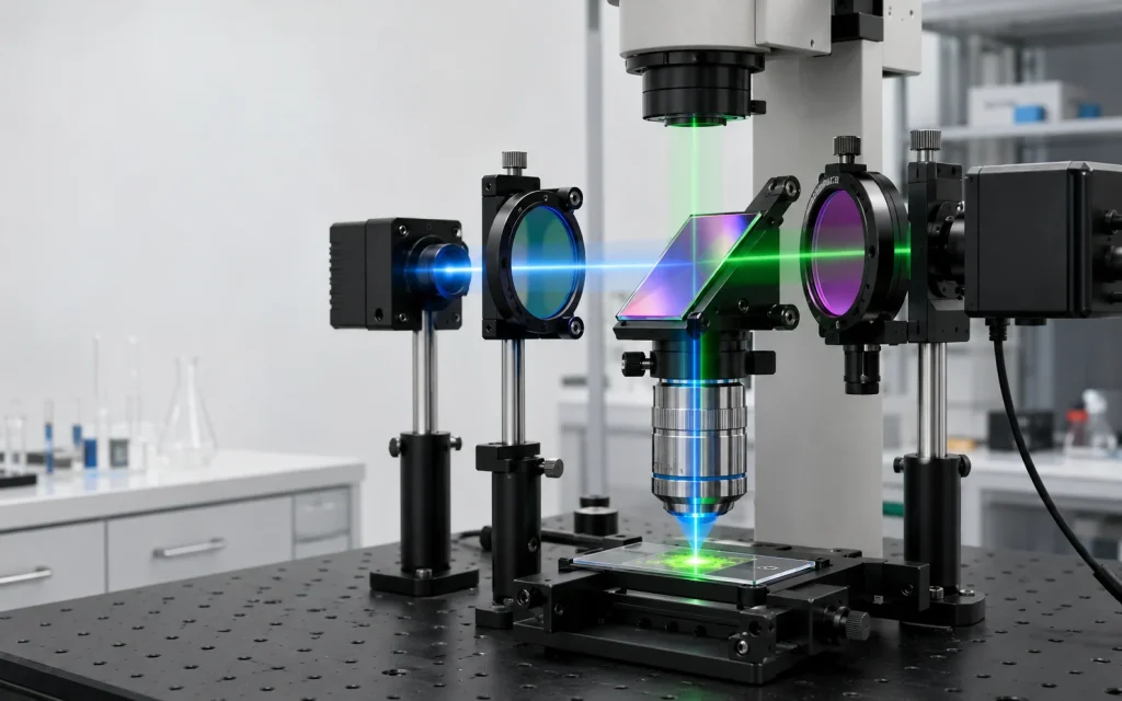
A fluorescence filter set is three components engineered as one spectral system: an excitation filter (exciter) that cleans up the illumination, a dichroic beamsplitter that separates excitation from emission, and an emission filter (emitter) that passes fluorescence and rejects everything else. Fluorescence filter set design basics reduce to placing four spectral edges inside the Stokes shift of your fluorophore, then deciding how much peak transmission you are willing to trade for blocking depth. Place the edges well and you get signal. Under-specify the blocking and you get a bright background that no amount of exposure time will fix.
Fluorescence filter set design basics: the three-filter architecture
A fluorophore absorbs a photon and re-emits at a longer wavelength. The wavelength difference between the absorption peak and the emission peak is the Stokes shift, and it is the only spectral room you have to work with.
The exciter is a bandpass filter centered on the absorption band. The dichroic sits at 45 degrees, reflects the excitation band toward the sample, and transmits the emission band toward the detector. The emitter is a bandpass or longpass filter centered on the emission band.
The ordering constraint is simple to state and hard to satisfy:
exciter long edge < dichroic transition wavelength < emitter short edge
The difficulty is that Stokes shifts are small. Fluorescein isothiocyanate (FITC) peaks near 495 nm in absorption and near 519 nm in emission, so you are placing three spectral boundaries inside roughly a 24 nm window while demanding six orders of magnitude of out-of-band rejection. Large Stokes shift dyes such as DAPI (4′,6-diamidino-2-phenylindole), roughly 358 nm to 461 nm, are far more forgiving and let you use wider, brighter passbands.
Where to place the edges, and what each choice costs
Widening the exciter collects more excitation power and gives you a brighter image, but it pushes the long edge closer to the emission band and increases bleedthrough. Narrowing it improves contrast and costs you photons.
The emitter choice is a similar trade:
- Longpass emitter: collects the full emission tail, maximizing signal. It also collects sample autofluorescence and any longer-wavelength dye, so it is a poor choice for multiplexing.
- Bandpass emitter: rejects long-wavelength background and isolates one channel cleanly. Expect to give up 20 to 40 percent of the collectible emission depending on how tightly you crop the tail.
Leave a guard band between the exciter long edge and the emitter short edge. Around 10 to 15 nm is typical for hard-coated filters with steep edges. Filters with softer transitions need more.
The general rule across the whole set: narrower bandwidth requires more coating layers, which lowers peak transmission, raises cost, and increases film stress on the substrate. You cannot push bandwidth, blocking depth, and flatness simultaneously without paying somewhere.
The datasheet parameters that determine whether the set works
| Parameter | Exciter | Dichroic | Emitter | Notes |
|---|---|---|---|---|
| Center wavelength (CWL) / transition wavelength | Specified at 0 deg AOI | Specified at 45 deg AOI | Specified at 0 deg AOI | Dichroic transition is quoted at the 50 percent transmission point |
| Full width at half maximum (FWHM) | 10 to 40 nm typical | n/a | 20 to 60 nm typical | Narrower means fewer photons |
| Peak / average transmission | >90 percent typical, hard-coated | >90 percent in passband | >90 percent typical, hard-coated | Soft-coated parts often land at 50 to 70 percent |
| Blocking range | Source spectrum, commonly 200 to 1100 nm | Narrower, application-dependent | Detector sensitivity range | Silicon detectors respond well past 900 nm |
| Edge steepness | <1 percent of edge wavelength | <1 to 2 percent | <1 percent | Steeper edges mean more layers |
| Angle of incidence (AOI) | 0 deg | 45 deg | 0 deg | Cone angle matters, see below |
| Substrate thickness | 1 to 5 mm | 1 to 3 mm | 1 to 5 mm | Thin dichroics flex, thick ones aberrate |
| Transmitted wavefront error | Relaxed | Critical if in imaging path | Relaxed to moderate | Often quoted as P-V at 632.8 nm |
| Surface quality (scratch-dig) | 60-40 typical | 60-40 typical | 60-40 typical | 40-20 for laser or high-contrast paths |
| Clear aperture | 85 to 90 percent of dimension | 85 to 90 percent | 85 to 90 percent | Dichroics are often rectangular for a 45 deg mount |
Surface quality is conventionally called out per MIL-PRF-13830B, with ISO 10110-7 as the metric alternative. Surface figure follows ISO 10110-5 or a simple P-V (peak to valley) callout in fractions of a wave.
For some modern hard-coated filters, thermal shifts can be only a few picometers per degree Celsius, but the magnitude and sign are design- and material-dependent.
Why angle of incidence changes the whole design
All interference filters blueshift as the angle of incidence increases. For an incident medium of index n0 in air:
λ(θ) = λ0 × sqrt(1 – (n0 / n_eff)² × sin²θ)
Here n_eff is the effective index of the coating stack, typically somewhere between 1.7 and 2.1 for sputtered designs using tantalum pentoxide (Ta2O5) or niobium pentoxide (Nb2O5) with silicon dioxide (SiO2). The exact value is design-specific and varies by supplier, so treat published shift curves as the authority rather than a hand calculation.
Two consequences follow.
Dichroics are designed at 45 degrees, not shifted to it. At 45 degrees the blueshift is roughly 7 to 8 percent, which is nearly 40 nm at 500 nm. You specify the transition wavelength as it behaves at 45 degrees. Asking a vendor for a “500 nm dichroic” without stating the angle is one of the most common ways to receive a part that does not work.
Cone angle smears every edge. For small angles the shift approximates to Δλ ≈ -λ0 θ² / (2 n_eff²). An f/2 beam has a half-angle near 14.5 degrees, which moves a 500 nm edge by a few nanometers and softens it, because every ray in the cone sees a slightly different filter. This is why infinity-corrected microscopes put the filter set in collimated space between the objective and the tube lens.
At 45 degrees the coating also separates s-polarized and p-polarized light. The two edges typically sit 5 to 15 nm apart, which softens the effective transition and partially polarizes light in that region. For fluorescence anisotropy or fluorescence polarization assays, this is a first-order design concern rather than a footnote.
Where the background actually comes from
In a typical epifluorescence system the excitation photon flux at the sample exceeds the emission flux reaching the detector by six orders of magnitude or more. OD6 blocking is not conservatism, it is the level at which leakage becomes comparable to a dim signal.
- Blocking range too narrow. Light emitting diode (LED) and arc lamp sources emit far outside the passband. If exciter blocking stops at 800 nm and your silicon camera is still sensitive at 1000 nm, near-infrared leakage arrives unblocked.
- Substrate and cement autofluorescence. Filter glass and the optical cement in laminated assemblies fluoresce under intense blue and ultraviolet excitation. That fluorescence is generated after the exciter, so no amount of exciter blocking helps. Fused silica and single-substrate hard-coated construction reduce it.
- Mount and housing scatter. Blackened, threaded, and light-trapped housings matter as much as the coating when you are chasing OD6.
Deep blocking has a mechanical cost. A hard-coated bandpass with OD6 blocking can run well over 100 layers and several micrometers of total thickness, and that film stress bows the substrate. Blocking depth and surface flatness pull against each other, which is exactly why dichroic flatness specifications are harder to hit than bandpass flatness specifications.
Hard-sputtered versus soft-coated construction
| Attribute | Hard-sputtered (IBS, magnetron, IAD) | Soft-coated (evaporated, laminated) |
|---|---|---|
| Materials | Ta2O5, Nb2O5, TiO2, SiO2 | Zinc sulfide, cryolite, plus colored glass blockers |
| Peak transmission | Typically >90 percent | Typically 50 to 70 percent |
| Edge steepness | Steep, <1 percent of edge wavelength | Softer |
| Environmental stability | Non-hygroscopic, cleanable, long service life | Hygroscopic, degrades with humidity and heat |
| Construction | Single substrate | Multiple laminated elements with cement |
| Autofluorescence risk | Low | Higher, from cement layers |
| Cost | Higher unit cost | Lower unit cost |
Hard-sputtered coatings have become the default for anything in a live imaging or quantitative instrument. Soft-coated parts still appear in cost-sensitive or legacy equipment and in some deep ultraviolet designs where hard coating materials are not available. If you are specifying dichroic filters or a custom coating run for a fluorescence instrument, GIAI Photonics builds to a defined spectral curve rather than a catalog part number.
Flatness, wavefront, and the tilted plate problem
The dichroic sits in the imaging path, so its transmitted wavefront error affects image quality directly. Reflected flatness matters less in widefield epifluorescence, because the excitation path is not imaged, but it becomes critical in confocal, total internal reflection fluorescence (TIRF), and laser scanning systems where the reflected beam must stay diffraction-limited.
This creates a genuine conflict. Thin dichroic substrates near 1 mm flex under mounting stress and coating stress, degrading flatness. Thicker substrates hold figure better, but a plane-parallel plate tilted at 45 degrees in a converging beam introduces astigmatism and coma that scale with thickness.
The standard resolution is to keep the dichroic in collimated space and specify transmitted wavefront over the clear aperture, commonly at λ/4 P-V or better at 632.8 nm for imaging paths. If your architecture forces a dichroic into a converging beam, budget the astigmatism explicitly instead of discovering it at integration.
Mounting is part of the specification. A dichroic that meets flatness on an interferometer will not meet it in a cube that clamps it at three points under spring load.
Single-band versus multiband sets
Multiband sets image several fluorophores without swapping the dichroic, which eliminates the pixel registration shift that occurs when a tilted plate moves between exposures. Three configurations are standard:
- Full multiband: multiband exciter, dichroic, and emitter. Fastest, no moving parts, and the most crosstalk.
- Pinkel: single-band exciters on a wheel, one multiband dichroic, one multiband emitter. Better spectral separation with a single moving element.
- Sedat: single-band exciters and single-band emitters on wheels, one fixed multiband dichroic. Best separation and stable registration, since the dichroic never moves.
Multiband coatings need many more layers than single-band equivalents, so expect lower average transmission, softer edges, and tighter tolerancing on the coating run.
Common specification mistakes
- Quoting the dichroic wavelength without the angle. A transition wavelength means nothing until you state 45 degrees.
- Ignoring the illumination cone. A filter characterized at 0 degrees will blueshift and smear in a fast beam. Specify the AOI range you actually use.
- Blocking range shorter than the detector response. Specify blocking across the full source emission and full detector sensitivity, not just near the passband.
- Assuming dichroic blocking substitutes for emitter blocking. A dichroic typically delivers OD2 to OD3. The emitter carries the rejection.
- Buying three catalog filters separately. Individually correct parts can leave a gap or overlap when combined. Specify the set against the fluorophore and the source.
- Over-specifying cosmetics, under-specifying wavefront. A 20-10 scratch-dig on a filter in collimated space buys little. Transmitted wavefront error buys a lot.
How to choose
Start from the fluorophore excitation and emission spectra, then overlay the actual source spectrum, because an LED and a metal halide lamp will push you toward different exciter bandwidths. Decide next whether you need maximum sensitivity or maximum channel separation, since that single decision drives the longpass versus bandpass emitter choice. Then set blocking depth from your expected signal-to-background ratio, and only then look at mechanical format, clear aperture, and flatness.
Send the vendor the spectra and the optical layout, not just a list of wavelengths. Edge placement is a system decision.
FAQ
Can I use a filter set designed for FITC with GFP? Usually yes. Green fluorescent protein (GFP) and FITC have similar absorption and emission peaks, and most FITC sets pass GFP with acceptable efficiency. You will lose some signal because GFP absorbs slightly shorter, and a dedicated GFP set with a shifted exciter will be brighter. For quantitative work, compare the actual transmission curve against the GFP spectrum rather than relying on peak proximity.
Why is my background high even with an OD6 emitter? Check sources of light generated after the exciter. Substrate or cement autofluorescence in the filters, immersion oil, plasticware, and culture medium all fluoresce. Also verify the exciter blocking range extends across your full detector response, and inspect the housing for unblackened surfaces. OD6 blocking at the excitation wavelengths does not eliminate fluorescence or stray light generated downstream of the relevant filter.
Does the dichroic need to be flat if it is only a beamsplitter? Yes, if it sits in the imaging path. Transmitted wavefront error from the dichroic reaches the camera directly. Reflected flatness matters when the excitation beam must stay diffraction-limited, as in confocal, TIRF, or laser scanning. In widefield epifluorescence with an incoherent source, reflected flatness requirements are considerably more relaxed.
How much guard band should I leave between exciter and emitter? For hard-coated filters with steep edges, 10 to 15 nm between the exciter long edge and the emitter short edge is a workable starting point, with the dichroic transition placed inside that gap. Softer edges need more. The exact value depends on your required signal-to-background ratio and on how much of the emission tail you can afford to lose.
Should I worry about polarization in the dichroic? Only for some applications. At 45 degrees the s and p transitions separate by roughly 5 to 15 nm, which softens the edge and partially polarizes light in the transition region. This is irrelevant for routine intensity imaging but directly corrupts fluorescence anisotropy and polarization assays. If you measure polarization, specify the s and p curves.
Are hard-coated filters always the right choice? Not always, but usually. They deliver higher transmission, steeper edges, and stable performance without hygroscopic degradation, at higher unit cost. Soft-coated filters remain viable in cost-sensitive instruments and in some deep ultraviolet bands where hard-coating materials are unavailable. For any instrument expected to hold calibration for years, hard-coated construction is the safer specification.
For fluorescence work, the components in play are bandpass filters, dichroic filters, and custom optical coatings, all of which GIAI Photonics supplies to customer-defined spectral curves.
