
Technical Resources
How to Select a Dichroic Mirror for Fluorescence Systems
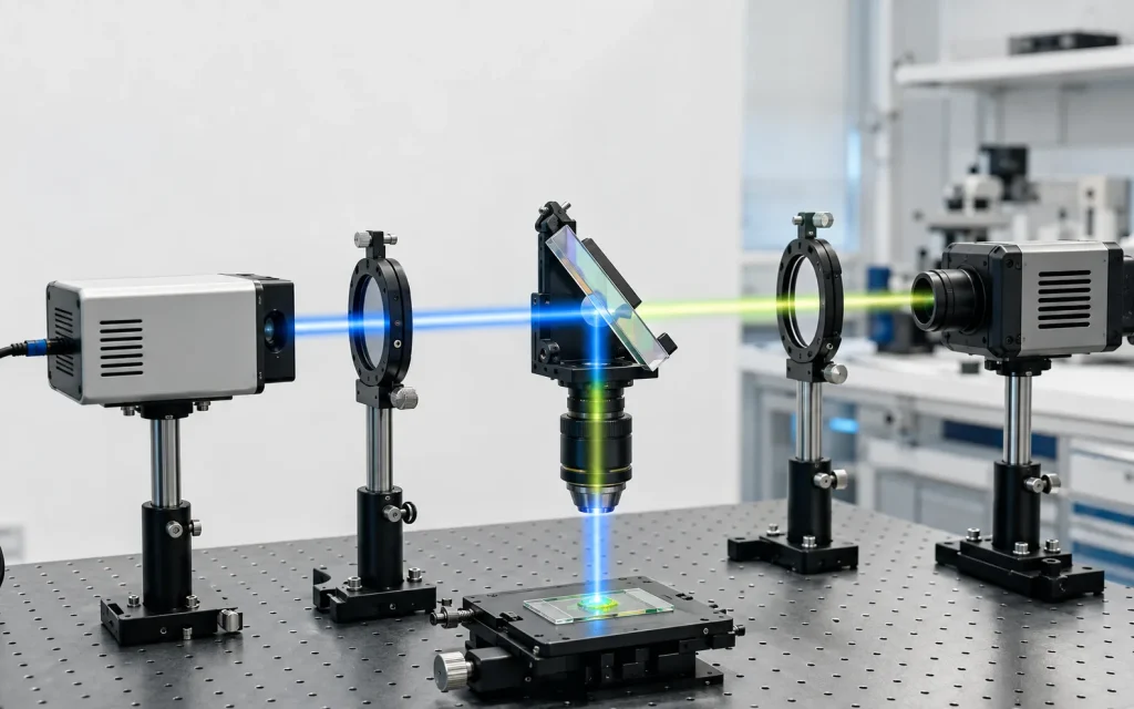
If your search starts with “dichroic mirror for fluorescence manufacturer,” the most important question is not simply who can supply the optic. The engineering task is to determine whether the dichroic mirror has the correct spectral transition, reflectance and transmission bands, angle-of-incidence behavior, polarization performance and physical quality for the fluorescence system in which it will operate.
A fluorescence dichroic mirror is normally an interference-coated optical element that separates excitation and emission light by wavelength. It works together with excitation and emission filters rather than replacing them. For system designers and technical procurement teams, the complete filter set should therefore be evaluated as one optical path.
What Does a Dichroic Mirror Do in a Fluorescence System?
In a typical epi-fluorescence configuration, illumination first passes through an excitation filter that selects the wavelength band needed to excite the fluorescent material. The filtered excitation beam then reaches a dichroic mirror positioned at an oblique angle, commonly around 45 degrees.
The dichroic coating is designed so that the excitation wavelength range is predominantly reflected toward the objective and sample. Fluorescence generated by the sample returns through the objective. Because the emitted fluorescence is normally shifted toward longer wavelengths, the dichroic mirror can transmit this emission toward the detector while directing much of the excitation energy away from the detection path.
Sample Fluorescence → Objective → Dichroic Mirror → Emission Filter → Detector
This reflect-shorter/transmit-longer configuration is common, but it is not a universal rule. The required transmission and reflection orientation depends on the optical architecture. Some instruments use different edge directions, multiple dichroics or sequential beam splitters to separate several fluorescence channels.
Why the Dichroic Mirror Matters to Fluorescence Detection
Fluorescence signals can be much weaker than the illumination used to excite them. The optical system therefore needs to deliver useful excitation energy to the sample while preventing reflected or scattered excitation light from overwhelming the detector.
The dichroic mirror contributes to this separation, but it does not determine system performance by itself. Residual excitation suppression also depends on the excitation filter, emission filter, optical geometry, stray-light control, objective, sample properties and detector response.
It is therefore misleading to evaluate a fluorescence dichroic only by a single value such as “high reflectivity.” Reflectance must be specified over the required excitation range, while transmission must be evaluated over the useful emission range.
Absorption is different from both reflection and transmission. For a real optical element, incident optical energy is distributed among reflection, transmission, absorption and small scattering losses. A dielectric dichroic mirror is generally designed to redirect unwanted wavelengths primarily by interference and reflection rather than by absorbing them.
1. Match the Dichroic Spectrum to Excitation and Emission Bands
The first selection step is to compare the full excitation and emission spectra of the fluorescence channel with the proposed filter characteristics.
Do not select the mirror from only the nominal peak wavelengths. Fluorescent materials usually have finite spectral width, and the light source, excitation filter, emission filter and detector each contribute their own spectral response.
For a common longpass-type fluorescence dichroic:
- the excitation band should fall within the high-reflectance region;
- the desired fluorescence band should fall within the high-transmission region;
- the transition between reflection and transmission should provide adequate separation between the two bands;
- the selected edge should not unnecessarily remove useful fluorescence near the short-wavelength side of the emission spectrum.
The highest possible peak transmission is not automatically the best criterion. For many imaging and sensing systems, transmission across the useful fluorescence band is more meaningful than a single peak value.
2. Understand the Transition Edge and Crossover Region
A dichroic mirror does not change instantaneously from 100% reflection to 100% transmission. Its spectral response contains a finite transition region.
The position and steepness of this transition are particularly important when the excitation and emission spectra are close together. A steeper transition can make better use of a small spectral separation, but the useful performance must still be evaluated at the specified angle of incidence and polarization state.
For an edge-type dichroic, terms such as cut-on wavelength, cut-off wavelength, crossover wavelength or transition width may be more useful than CWL and FWHM. CWL and FWHM are primarily used to describe bandpass filters and should not automatically be applied to every dichroic mirror.
3. Specify the Actual Angle of Incidence
Angle of incidence, or AOI, is one of the most important parameters for an interference-coated dichroic mirror.
Many fluorescence beam splitters operate near 45°, allowing an incoming beam to be redirected through approximately 90°. However, the thin-film interference condition changes when the incidence angle changes. Increasing the angle generally moves interference features toward shorter wavelengths.
For that reason, a dichroic designed for 0° incidence and one designed for 45° incidence are not optically interchangeable, even if their normal-incidence curves appear similar.
The manufacturer specification should state the AOI associated with the spectral curve. If the application has an AOI tolerance or a range of incident angles rather than one single angle, this should also be included in the optical requirement.
4. Consider the Angular Cone, Not Only the Chief Ray
Not every ray in a real instrument necessarily reaches the dichroic at exactly the same angle. A converging, diverging or otherwise non-collimated beam may contain a distribution of incidence angles.
Different angles can experience slightly different spectral transitions. The effective system response may therefore become broader or shifted compared with a measurement made using a narrow collimated beam at one nominal AOI.
This effect becomes particularly important when:
- the transition edge is located close to the fluorescence signal;
- the system uses a large angular cone;
- multiple spectral channels are tightly spaced;
- intensity uniformity across a field of view is important.
When possible, interference filters and dichroic mirrors should be placed in a suitably controlled portion of the optical path rather than assuming their catalog spectrum remains unchanged in every beam geometry.
5. Evaluate Polarization at Oblique Incidence
At oblique incidence, s-polarized and p-polarized light do not necessarily produce identical spectral responses in a multilayer dielectric coating.
At approximately 45°, the difference between the two polarization states can shift or broaden the apparent transition region. This may matter even in systems described as using unpolarized light because the measured system response represents contributions from both polarization components.
If the illumination is strongly polarized, such as in some laser-based fluorescence systems, separate s- and p-polarization specifications may be more useful than a single averaged curve.
For polarization-sensitive applications, procurement documentation should clearly state:
- design AOI;
- polarization state;
- required reflection band;
- required transmission band;
- acceptable transition position or tolerance.
6. Distinguish Transmission, Reflection and Optical Density
Transmission and reflectance are normally expressed as percentages or fractions of incident optical power. Optical density describes attenuation and is defined logarithmically from transmission.
For example, an OD value should not be interpreted as a reflectance specification. An optical filter can have low transmission because light is reflected, absorbed or both, depending on the design.
In a fluorescence filter set, deep blocking requirements are often particularly important for the excitation and emission filters. The dichroic provides wavelength routing, while the emission filter supplies additional rejection of excitation leakage before the detector.
For this reason, a specification such as “high transmission and high reflection” is incomplete unless the wavelength intervals and measurement conditions are stated.
7. Substrate Selection Is Part of the Optical Design
The coating determines most of the wavelength-selective behavior, but the substrate still affects the finished component.
Relevant substrate considerations can include:
- transmission range;
- refractive index;
- homogeneity;
- thermal properties;
- physical thickness;
- surface figure capability;
- environmental requirements.
Do not confuse the transmission range of the bare substrate with the spectral performance of the finished coated dichroic. The complete optic includes both the substrate and coating system.
8. Flatness, Surface Quality and Wavefront Are Different Specifications
Mechanical and imaging requirements should be specified separately from spectral performance.
| Parameter | What It Describes | Why It May Matter |
|---|---|---|
| Surface quality | Cosmetic defects such as scratches and digs | Relevant to scatter, inspection criteria and sensitive beam paths |
| Surface flatness | Deviation of a surface from an ideal plane | Can affect reflected wavefront quality |
| Parallelism | Angular relationship between opposite substrate surfaces | Can influence transmitted beam deviation and ghost geometry |
| TTV | Total thickness variation across the optic | Important for mechanical integration and some precision assemblies |
| Transmitted wavefront | Wavefront distortion after light passes through the complete optic | Important in imaging, collimated beams and precision optical systems |
A component can have good cosmetic surface quality without having sufficiently low wavefront error, and excellent flatness does not automatically define parallelism or TTV. These specifications should not be treated as interchangeable.
9. Watch for Ghost Reflections and Back-Surface Effects
A dichroic mirror is a plate with at least two optical interfaces. The primary coating performs the intended wavelength separation, while the opposite surface can also generate a Fresnel reflection unless it is appropriately controlled.
Depending on system geometry, this secondary reflection can create a displaced ghost beam, unwanted background or stray-light path.
An anti-reflection treatment on the appropriate secondary surface, suitable substrate geometry and correct mounting orientation can reduce these effects. The actual requirement should be determined from the optical layout rather than assuming every fluorescence system needs the same construction.
10. Single-Band and Multiband Fluorescence Systems Need Different Strategies
A single-channel system can often use one excitation band, one edge-type dichroic and one emission band. Multichannel instruments are more complex because several fluorescence spectra may overlap.
A multiband dichroic can contain several reflection and transmission regions within one coating design. Alternatively, multiple dichroics can be used sequentially to separate different wavelength ranges onto different detectors.
Multichannel designs require attention to cumulative transmission losses, spectral overlap, channel crosstalk, AOI and polarization effects at every beam splitter in the optical path.
A mirror that performs correctly by itself can still produce an unsuitable system result if its transition region conflicts with another filter or removes part of a neighboring fluorescence channel.
How to Evaluate a Dichroic Mirror for Fluorescence Manufacturer
When comparing manufacturing options, evaluate the technical definition of the optic rather than relying on generic descriptions such as “high transmission,” “high reflection” or “fluorescence grade.”
A useful engineering specification should identify the optical conditions under which the component is expected to operate.
- excitation wavelength range;
- fluorescence emission wavelength range;
- required reflection band and minimum reflectance;
- required transmission band and minimum or average transmission;
- design angle of incidence;
- AOI tolerance or angular range if applicable;
- polarization condition;
- transition-edge requirements;
- substrate material and thickness;
- clear aperture;
- part dimensions and dimensional tolerances;
- surface quality;
- flatness or wavefront requirement where relevant;
- environmental or durability conditions if the instrument requires them;
- measurement conditions used for spectral acceptance.
For a custom design, the spectral specification should ideally define acceptance bands rather than only a nominal crossover wavelength. This avoids ambiguity between a theoretical coating design and the actual performance needed by the instrument.
Example of a Better Specification Approach
Suppose an instrument uses blue excitation and detects a longer-wavelength green fluorescence signal. A weak specification might state only:
“45° fluorescence dichroic mirror with high reflection and high transmission.”
This leaves important questions unanswered.
A more useful specification defines the required reflection wavelength interval, transmission wavelength interval, minimum performance within each interval, design AOI, polarization condition and relevant mechanical requirements.
The exact wavelength values should be determined from the source spectrum, fluorescence spectrum, excitation and emission filters, detector sensitivity and system optical layout. They should not be copied from an unrelated fluorescence channel.
Common Selection Mistakes
Using a 0° spectral curve for a 45° application
Interference coatings are angle-sensitive. Always confirm the spectral response at the intended AOI.
Choosing from fluorophore peak wavelength alone
Use the complete useful excitation and emission ranges rather than only their peak values.
Optimizing peak transmission only
System signal depends on usable transmission across the required spectrum, not merely the highest point of a curve.
Ignoring polarization
Oblique-incidence dichroics can behave differently for s and p polarization, especially near the transition region.
Treating the dichroic as the only blocking element
Excitation suppression normally depends on the entire fluorescence filter set and optical architecture.
Confusing substrate performance with coated-component performance
A transparent substrate does not define the final transmission and reflection characteristics of a multilayer-coated optic.
Conclusion
Selecting a fluorescence dichroic mirror is a system-level spectral matching problem. Start with the excitation and fluorescence spectra, then define which wavelengths must be reflected and which must be transmitted.
Next, specify the real operating conditions: AOI, angular range, polarization, substrate, transition edge and any wavefront or surface requirements. Finally, evaluate the dichroic together with the excitation filter, emission filter, detector and optical layout.
For engineers evaluating a dichroic mirror for fluorescence manufacturer, a well-defined optical specification is more valuable than a generic request for high transmission or high reflectivity. The closer the specification represents the actual instrument geometry and spectral requirements, the easier it becomes to evaluate whether a proposed dichroic mirror is appropriate for the system.
Frequently Asked Questions
What is a dichroic mirror in fluorescence microscopy?
A dichroic mirror is a wavelength-selective optical beam splitter used to separate excitation light from emitted fluorescence. In a common epi-fluorescence arrangement, it reflects the shorter-wavelength excitation band toward the sample while transmitting longer-wavelength fluorescence toward the detector. It normally works together with an excitation filter and an emission filter. The exact reflection and transmission bands depend on the fluorescence channel and optical layout, so not every fluorescence dichroic uses the same crossover wavelength or spectral configuration.
Why are fluorescence dichroic mirrors commonly used at 45 degrees?
A 45° orientation allows the dichroic mirror to redirect an incoming beam by approximately 90°, which is convenient for combining illumination and detection through the same objective. However, the coating must be designed or specified for that operating angle. Thin-film interference spectra change with incidence angle, so a component characterized at normal incidence should not be assumed to have the same transition wavelength at 45°. Polarization behavior also becomes more important at oblique incidence.
How do I choose the crossover wavelength of a fluorescence dichroic?
Choose the transition region from the full excitation and emission spectra rather than from one nominal wavelength. The excitation band should remain in the intended reflection region while as much useful fluorescence as practical is retained in the transmission region. The excitation filter, emission filter, detector sensitivity and spectral overlap between channels should also be considered. In tightly spaced fluorescence channels, transition steepness and AOI tolerance may become especially important.
Does a dichroic mirror replace the fluorescence emission filter?
No. A dichroic mirror primarily routes different wavelength regions into different optical paths, while an emission filter provides additional spectral selection before the detector. Some excitation light can remain because of imperfect reflection, sample scattering, optical reflections or stray light. The emission filter helps suppress this residual excitation and limits detection to the required fluorescence band. The required blocking performance should therefore be evaluated for the complete filter set rather than assigned to the dichroic alone.
What information should be provided for a custom fluorescence dichroic mirror?
Provide the required reflection and transmission wavelength ranges, performance targets, design AOI, polarization condition and any allowed AOI range. Also define dimensions, clear aperture, substrate requirements and relevant surface or wavefront tolerances. If the optic will operate in a converging beam, near a sensitive detector or in a multichannel fluorescence system, include this information because angular distribution, ghost reflections and neighboring spectral channels can influence the most suitable coating design.
