
Technical Resources
F-Theta Lens vs Standard Focusing Lens
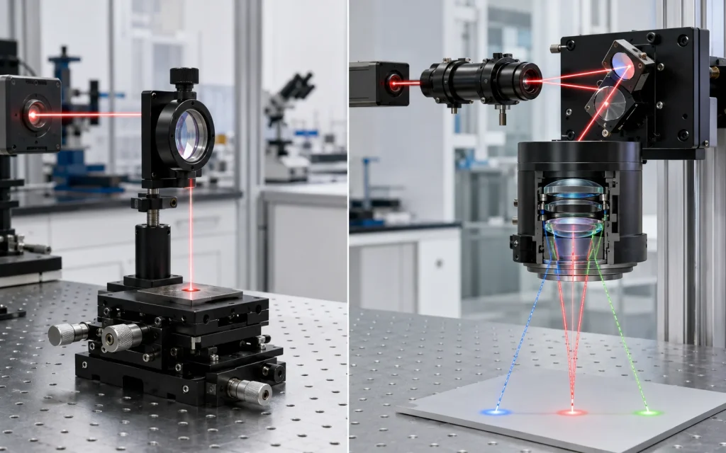
The practical difference in an F-theta lens vs standard focusing lens comparison is the job each optic is designed to perform. A standard focusing lens is normally chosen to form a good focus at one on-axis location, or within a limited field defined by its optical design. An F-theta lens is designed for a scanned beam: it focuses changing input angles onto a substantially flat work plane while controlling the relationship between scan angle and spot position.
What “Standard Focusing Lens” Means Here
“Standard focusing lens” is a broad engineering term, not one formal optical prescription. It may refer to a plano-convex lens, bi-convex lens, asphere, achromat or multi-element objective selected to bring a collimated or divergent beam to a focus. Its exact behavior depends on conjugates, numerical aperture, wavelength, beam quality and aberration correction.
In a fixed-beam setup, the lens is aligned to the optical axis and the target is placed near the focal plane. Other coordinates can be reached by translating the workpiece or focusing head, without asking the lens to correct a large angular scan field.
Problems arise when the same lens is placed after a scanner and asked to focus beams entering at increasingly large angles. A conventional lens that was not designed for this geometry may show field curvature, astigmatism, coma, changing spot shape, vignetting and nonlinear position mapping. These are off-axis system effects; they should not be interpreted as evidence that all standard focusing lenses are poor optics.
What an F-Theta Lens Does Differently
An F-theta lens—also called a scan lens or flat-field scanning objective—is usually a multi-element assembly positioned after the scan mirrors. The scanner changes the incoming beam angle, and the lens converts that angle into a focused position on the work surface.
The ideal one-dimensional mapping is:
Here, y is image height or spot displacement, f is effective focal length, and θ is the optical scan angle in radians. A conventional rectilinear imaging relationship is commonly written as y = f tan θ. The F-theta design deliberately controls distortion so that spot position more closely follows the linear fθ relationship. This simplifies scan control, although a real two-axis system still requires calibration for residual lens distortion, mirror separation, scanner dynamics, mounting errors and controller behavior.
At the same time, the optical design reduces field curvature so the best-focus surface lies close to the flat work plane. It also controls off-axis aberrations to keep the focused spot usable across the specified scan field. “Flat field” does not mean perfectly identical spot size, wavefront quality or incidence angle at every coordinate; the allowable variation must be defined in the lens and system specifications.
F-Theta Lens vs Standard Focusing Lens: Direct Comparison
| Engineering factor | F-theta lens | Standard focusing lens |
|---|---|---|
| Primary task | Focus an angularly scanned beam across a defined work field | Produce a focus at a fixed position or over a limited design field |
| Typical beam motion | Galvanometer or polygon scanner changes beam angle | Beam is fixed; part, stage or focusing head may move |
| Focal surface | Corrected toward a substantially flat image plane | May be curved when used off axis unless specifically corrected |
| Position mapping | Designed around approximately linear y = fθ mapping | Not normally optimized for F-theta scan mapping |
| Off-axis spot control | Optimized over a stated scan angle, beam diameter and wavelength | Performance may decline rapidly outside its intended field |
| Chief-ray angle at workpiece | Varies in a normal non-telecentric design; reduced by a telecentric design | Usually not specified for wide-field galvo scanning |
| Mechanical complexity | Requires correct scanner spacing, aperture matching and calibration | Often simpler for fixed-focus or stage-based processing |
| Typical uses | Laser marking, scanning, micromachining, drilling and selected additive processes | Fixed-point focusing, cutting heads, laboratory beam delivery and stage-scanned work |
Four Performance Differences That Matter in Practice
1. Flatness of the Focal Surface
A flat workpiece cannot follow a curved best-focus surface. If focus moves axially as the beam scans toward the field edge, spot size and irradiance at the material change. An F-theta lens is corrected to reduce this defocus over its specified field. The remaining field curvature should still be compared with the process depth of focus and the flatness tolerance of the workpiece.
2. Scan Linearity and Distortion
The F-theta condition makes spot displacement approximately proportional to optical scan angle. Actual lenses have residual F-theta distortion, commonly expressed as the deviation between the real image height and the ideal fθ position. Scanner control software can compensate for repeatable geometric error, but correction data cannot repair a defocused or severely aberrated spot. Optical performance and coordinate calibration are separate requirements.
3. Spot Size and Spot Shape Across the Field
For a near-Gaussian beam, focused spot size generally increases with wavelength, beam-quality factor M² and focal length, and decreases as the usable input beam diameter increases. That relationship is only a starting estimate. Truncation at the galvo or lens aperture, lens aberrations, thermal effects and the chosen spot-size definition can change the result. Compare center, edge and corner performance under the actual beam diameter—not only the smallest nominal spot listed in a datasheet.
4. Incidence Angle and Telecentricity
A standard non-telecentric F-theta lens can provide a flat scan field while the focused beam becomes increasingly oblique toward the edges. A telecentric F-theta design reduces this chief-ray angle so the beam reaches the workpiece more nearly normal to the surface. This can matter in drilling, deep structuring and processes sensitive to wall angle or feature geometry. Telecentricity is an additional design property; it is not implied by the term “F-theta.”
When a Standard Focusing Lens Is the Better Choice
A standard lens remains the direct solution when the process occurs at one position, the field is small, or mechanical motion is acceptable. Examples include focusing into a fiber, detector, sample cell or fixed processing point; moving a sample with an XY stage; or using a cutting head that maintains focus relative to the surface.
It may also be preferred when very high numerical aperture or the smallest attainable on-axis spot matters more than rapid wide-field scanning. A scan lens must balance field size, aberration correction, working distance, aperture and packaging. A purpose-designed on-axis objective can concentrate its optical correction on a much narrower set of field conditions.
When an F-Theta Lens Is Required
An F-theta lens is normally the correct architecture when an angular scanner must position a focused beam over a flat area at high speed. Typical examples include laser marking, engraving, surface texturing, PCB processing, micro-drilling, selected welding or cleaning processes, and powder-bed laser scanning.
The requirement becomes stronger as scan angle, field size and positional tolerance increase. At very small angles, tan θ and θ are close, so the mapping difference may be minor. Even then, field curvature and off-axis aberrations must be checked. For unusually large fields or non-flat three-dimensional surfaces, a dynamic-focus or three-axis scan head may be more suitable than expecting a fixed F-theta lens to cover the entire axial range.
How to Specify the Lens at System Level
Lens selection should begin with the laser, scanner and process as one system. The following inputs are more useful than a request based only on wavelength and focal length:
Wavelength or spectral band, CW or pulsed operation, average power, pulse energy, pulse width, repetition rate, polarization and M².
1/e² beam diameter at the lens, divergence, beam-expander ratio and allowed aperture truncation.
Galvo or polygon type, clear aperture, mirror dimensions, optical scan angle, mirror separation and lens-to-scanner distance.
Required X–Y area, flatness, positional tolerance, edge performance and whether the field is rectangular or circular.
Target spot definition, depth of focus, working distance, acceptable spot variation and required telecentricity.
Mounting thread, envelope, environmental conditions, protective window, contamination control and calibration method.
Coating and substrate must be evaluated at the operating wavelength and angle distribution. High transmission or low reflection does not by itself establish laser-induced damage resistance. For pulsed systems, the damage assessment also depends on pulse duration, pulse energy, repetition rate, beam size, coating design, cleanliness and test method. A component described for 1064 nm, for example, is not automatically suitable for every 1064 nm source.
Common Selection Mistakes
- Comparing focal length alone. Two lenses with the same effective focal length can have different fields, apertures, distortion, working distances and telecentricity.
- Using mechanical mirror angle as optical scan angle. For a rotating mirror, optical beam deflection is approximately twice the mechanical mirror rotation; datasheet conventions must be confirmed.
- Assuming a larger field has no resolution trade-off. A larger field often involves a longer focal length or larger scan angle, either of which can affect spot size and edge performance.
- Ignoring scanner-to-lens spacing. Moving the entrance pupil away from the design position can cause vignetting, alter the usable field and increase telecentricity error.
- Treating software correction as optical correction. Calibration can improve coordinate mapping, but it cannot restore focus quality lost to aberration, clipping or field curvature.
Conclusion
The key distinction between an F-theta lens and a standard focusing lens is field behavior. A standard lens is usually the efficient choice for a stationary or mechanically positioned focus. An F-theta lens is engineered for angular scanning across a flat work plane, with controlled off-axis focus and approximately linear scan mapping.
For system selection, define the scan field, wavelength, beam diameter, spot requirement, scanner geometry, working distance and incidence-angle tolerance together. That makes it possible to judge whether a conventional focusing optic, a non-telecentric F-theta lens, a telecentric scan lens or a dynamic-focus architecture fits the real process.
Frequently Asked Questions
Can a standard focusing lens be used with a galvanometer scanner?
Yes, but only when its performance is acceptable over the required scan angle and field. At small angles, a conventional lens may provide usable results, especially when tolerances are moderate. As the field grows, however, field curvature, coma, astigmatism, vignetting and nonlinear position mapping can become significant. The correct test is not whether a spot appears at the center, but whether focus position, spot shape and coordinate accuracy remain within specification at the center, edges and corners.
Does an F-theta lens produce the same spot size everywhere?
No. It is designed to limit spot-size and focus variation across a specified field, but some residual change normally remains. The result depends on wavelength, beam diameter, M², scan angle, aberrations, aperture truncation and manufacturing tolerances. Datasheets may also use different spot definitions, such as geometrical diameter, Airy diameter or Gaussian 1/e² diameter. Engineers should request field-dependent spot data and confirm the definition and input conditions used.
Is every F-theta lens telecentric?
No. A conventional F-theta lens can focus onto a flat field while the chief-ray angle changes across that field. A telecentric F-theta lens is additionally designed to keep the focused beam closer to perpendicular to the work surface. This may improve feature geometry in drilling, deep processing or angle-sensitive applications, but it generally requires larger front optics and may reduce the available field for a given package size.
How does focal length affect scan field and spot size?
A longer focal length generally produces more image displacement for the same scan angle and therefore can support a larger field, but it also tends to create a larger focused spot for the same wavelength and input beam diameter. It usually increases working distance as well. These are system-level trends rather than fixed guarantees because usable field, aperture, lens prescription, beam quality and aberration correction also affect the final result.
Can one F-theta lens be used at several laser wavelengths?
Only if its optical design, materials and coating are specified for those wavelengths. Refractive index changes with wavelength, so focal length, focus position and aberrations can shift. Coating transmission and laser-damage behavior also vary with wavelength, angle and pulse conditions. A lens labeled for one wavelength should not be assumed to work at another. Multi-wavelength or color-corrected scan lenses exist, but their usable spectral band and performance limits must be verified.
