
Technical Resources
How Narrowband Filters Improve LiDAR Signal-to-Noise Ratio
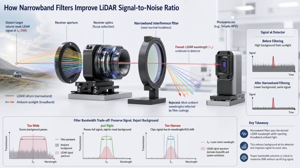
A narrowband optical filter improves LiDAR signal-to-noise ratio primarily by reducing the amount of broadband ambient light that reaches the receiver detector while preserving the wavelength of the returned laser pulse. The principle is straightforward, but the engineering trade-off is not: making the passband narrower reduces background photons only as long as the filter still transmits the complete useful signal under wavelength drift, manufacturing tolerance, temperature variation, angle of incidence, and the receiver’s angular cone.
For that reason, understanding how narrowband filters improve LiDAR signal-to-noise ratio requires more than comparing nominal FWHM values. The filter has to be treated as part of the complete receiver rather than as an isolated optical component.
Where the Narrowband Filter Sits in a LiDAR Receiver
A direct-detection LiDAR receiver collects more than the reflected laser pulse. Its receiving optics can also collect sunlight reflected from the target and surrounding scene, artificial illumination, optical stray light, and radiation from other sources within the detector’s spectral sensitivity range.
A simplified receiving path can be represented as:
The narrowband filter performs spectral discrimination. It transmits a limited wavelength interval around the LiDAR operating wavelength and attenuates wavelengths outside that interval.
This is different from temporal filtering, spatial filtering, electronic thresholding, or digital signal processing. Those methods may also improve detection performance, but they operate on different dimensions of the noise problem.
Why Ambient Light Reduces LiDAR SNR
Outdoor LiDAR systems often operate in the presence of broadband solar radiation. Even when the transmitter emits at one narrow wavelength,the detector may remain sensitive across a spectral range spanning tens or even hundreds of nanometers.
Without sufficient spectral filtering, optical energy across that broader detector-response range can generate background photocurrent or background photon counts.
A useful conceptual expression for the received background is:
where:
- L(λ) represents the spectral radiance or irradiance contributing to the receiver;
- R(λ) represents detector spectral responsivity or photon-detection efficiency;
- Tfilter(λ) represents the spectral transmission of the complete filter;
- the integration covers wavelengths capable of contributing measurable background at the detector.
This expression explains why specifying only the center wavelength of a LiDAR filter is insufficient. What matters is the combination of its passband and its rejection over wavelengths where ambient energy and detector sensitivity overlap.
How a Narrower Passband Reduces Background Photons
Consider a laser return concentrated within a narrow spectral interval. If the receiver initially admits a relatively broad optical band, much of that spectral window contains background radiation but no useful LiDAR signal.
Reducing the filter bandwidth removes part of this unnecessary background.
Over a sufficiently small wavelength interval where the ambient spectral density and detector response do not change dramatically, background optical power can be approximated as proportional to the effective filter bandwidth:
where Δλ is the effective optical passband width.
For example, under that simplified assumption, reducing the accepted bandwidth from 20 nm to 2 nm would reduce the in-band broadband background power by approximately a factor of ten. This is an optical-background comparison, not a claim that complete system SNR automatically improves by ten times.
Signal-to-Background Ratio Is Not the Same as Signal-to-Noise Ratio
This distinction is important in LiDAR engineering.
If useful signal power remains unchanged while background optical power decreases by ten times, the optical signal-to-background ratio can improve by approximately ten times.
Signal-to-noise ratio behaves differently because noise is statistical and can include several terms.
In a background shot-noise-limited receiver, the noise amplitude associated with detected background photons approximately follows the square root of the number of background photons:
Therefore, if reducing bandwidth decreases the background photon count by a factor of ten while useful signal remains unchanged, the SNR improvement associated with that background term is closer to:
This relationship applies only when background photon shot noise dominates the relevant noise budget. A practical LiDAR receiver can also be affected by detector dark current or dark count rate, avalanche excess noise, amplifier noise, readout noise, quantization effects, and signal shot noise.
Once those other terms dominate, further optical-background reduction may provide progressively less improvement in total SNR.
Why the Narrowest Filter Is Not Automatically the Best Filter
An idealized laser may appear monochromatic, but a real LiDAR receiver has a wavelength tolerance budget.
The useful return reaching the filter can vary because of:
- laser linewidth;
- nominal laser wavelength tolerance;
- laser wavelength drift with temperature and operating conditions;
- filter center-wavelength manufacturing tolerance;
- filter temperature dependence;
- angle-of-incidence shift;
- the angular cone produced by the receiver optics;
- polarization effects at non-normal incidence.
If the specified FWHM becomes narrower than the accumulated wavelength and angular uncertainty, part of the return signal moves onto the passband edge or outside the useful transmission region.
At that point the filter begins reducing the signal it was intended to preserve.
The correct design target is therefore not simply the minimum manufacturable FWHM. It is the narrowest effective spectral window that continues to provide the required signal transmission across the complete operating tolerance range.
Peak Transmission Matters Alongside FWHM
A narrower passband has limited value if useful-signal transmission falls substantially.
The received signal after the filter can be represented conceptually as:
where Tsignal is the transmission experienced by the actual laser return under the relevant wavelength, AOI, polarization, and temperature conditions.
This is why peak transmission and average transmission should not be treated as interchangeable specifications.
A high peak transmission measured at one wavelength and at 0° incidence does not prove that the complete returned signal will experience the same transmission inside the installed receiver.
AOI Can Shift a Narrowband Filter Away From the Laser Wavelength
Most high-selectivity LiDAR filters are based on multilayer interference coatings. Their spectral characteristics depend on angle of incidence.
As the incidence angle increases from the design condition, the passband of a conventional interference filter generally shifts toward shorter wavelengths. The effect is commonly called an angular blue shift.
A simplified relationship often used to describe the tendency is:
where λ(0) is the reference center wavelength, θ is the incidence angle, and neff is an effective refractive-index term representing the coating design.
The equation is useful for understanding the direction and approximate behavior of the shift, but the actual spectral response should be obtained from the specific coating design or measured filter.
A receiver usually contains an angular distribution, not one AOI
The problem becomes more important when a filter operates inside a converging or diverging beam. Rays across the optical cone strike the filter at different angles.
Each ray can therefore experience a slightly different spectral response. The system-level result may be a shifted or effectively broadened passband compared with a normal-incidence spectrophotometer measurement.
For a very narrow filter, even a small angular shift can consume a significant part of the wavelength budget.
Where the receiver architecture permits it, locating a highly angle-sensitive filter in a more nearly collimated section of the optical path can make spectral control easier. Packaging, clear aperture, ghost reflections, cost, and other optical constraints must also be considered.
Field of View and Filter Bandwidth Solve Different Parts of the Same Problem
Spectral bandwidth is not the only way to reduce sunlight reaching a LiDAR detector.
The receiver field of view controls how much of the illuminated scene contributes background radiation. A narrow spatial acceptance angle can substantially reduce unwanted light, provided that it remains compatible with transmitter-receiver alignment, scanning geometry, target motion, and system tolerances.
This creates two complementary forms of rejection:
- Spectral rejection: accept wavelengths close to the laser and reject other wavelengths.
- Spatial rejection: accept light from the required viewing direction while excluding unnecessary scene area.
A high-performance receiver normally considers both rather than asking the optical filter to solve the complete background-light problem.
Why Out-of-Band OD Is as Important as Passband Width
FWHM tells an engineer how wide the main transmission band is. It does not tell them how effectively the filter suppresses radiation farther away from that band.
Out-of-band rejection is commonly expressed using optical density:
where T is fractional transmission.
For example:
| Optical Density | Fractional Transmission | Percentage Transmission |
|---|---|---|
| OD2 | 10−2 | 1% |
| OD3 | 10−3 | 0.1% |
| OD4 | 10−4 | 0.01% |
| OD5 | 10−5 | 0.001% |
However, an OD value without a wavelength interval is incomplete.
A detector can respond over a much wider spectral region than the LiDAR laser. Even a small amount of leakage integrated across that broad range may generate meaningful background.
A useful specification therefore defines both:
- the required optical density;
- the wavelength range over which that blocking must be maintained.
The appropriate OD blocking range should follow the actual detector response, ambient spectrum, internal emitters, and allowable background budget rather than a generic filter specification.
905 nm and 1550 nm Receivers Do Not Have the Same Filtering Problem
The filtering principle is similar at 905 nm and 1550 nm, but the complete receiver conditions differ.
| Engineering Factor | 905 nm Region | 1550 nm Region |
|---|---|---|
| Detector platform | Silicon-based detectors are commonly usable | SWIR-sensitive detector technology is normally required |
| Ambient spectrum | Depends on terrestrial solar spectrum and scene conditions | Different solar spectral background; not zero |
| Required blocking range | Should follow the selected silicon detector response | Should follow the selected SWIR detector response |
| FWHM selection | Set by source and receiver tolerance budget | Also set by source and receiver tolerance budget |
| AOI behavior | Interference passband shifts with incidence angle | The same physical issue remains relevant |
This is why a 905 nm vs 1550 nm LiDAR optical filter comparison should include more than nominal wavelength. Detector responsivity, source behavior, eye-safety design, atmospheric and solar conditions, and receiver architecture all influence the final system.
Direct ToF and FMCW LiDAR May Need Different Optical Filtering Strategies
The benefit of a narrowband filter also depends on receiver architecture.
Direct time-of-flight LiDAR
In direct ToF systems, the receiver detects returning optical pulses against ambient photons and detector/electronic noise. Optical bandpass filtering can therefore play a major role in reducing background photon flux before detection.
Systems using PIN photodiodes, APDs, SPADs, or SiPM-type detectors can have different noise terms and saturation behavior, so the optimum filter cannot be determined independently from the detector.
Coherent FMCW LiDAR
A coherent receiver obtains strong spectral and phase selectivity through optical mixing with a local oscillator. Incoherent ambient light is therefore rejected differently from direct detection.
A receive filter can still be useful for limiting unwanted optical loading, preventing detector saturation, rejecting strong interfering wavelengths, or controlling stray light, but the optimum passband need not follow the same rules as a direct ToF receiver.
Five Parameters That Should Be Specified Together
For a LiDAR narrowband filter, the following parameters should be treated as an interconnected specification rather than separate datasheet numbers.
1. Center wavelength
CWL should be aligned with the actual source wavelength after considering the operating temperature range, source tolerance, filter tolerance, and installed AOI.
2. FWHM
FWHM should be narrow enough to reduce unnecessary broadband background but wide enough to preserve the useful return across the complete wavelength and angular tolerance budget.
3. In-band transmission
Specify transmission over the useful spectral region rather than relying only on a single peak-transmission number when the application requires a broader guaranteed region.
4. Blocking OD and blocking range
Blocking requirements should correspond to wavelengths where the detector is meaningfully responsive and where unwanted optical radiation can enter the system.
5. AOI and angular cone
State the nominal angle of incidence as well as the expected angular distribution. A spectrum specified only at 0° AOI may not represent installed performance in a wide-angle or fast optical system.
A Practical LiDAR Filter Specification Workflow
- Define the laser spectrum. Record nominal wavelength, linewidth, production tolerance, and temperature-dependent wavelength change.
- Define the detector response. Determine the wavelength interval over which unwanted photons can create an electrical response or photon count.
- Estimate ambient background. Include sunlight or other relevant optical sources and consider target reflectance, field of view, and receiver aperture.
- Build the wavelength tolerance budget. Combine source variation, filter tolerance, temperature effects, and AOI-related spectral movement.
- Set the preliminary FWHM. Choose a band that preserves the return under the required conditions rather than selecting the smallest available value.
- Define blocking by wavelength range. Specify OD where suppression materially affects detector background.
- Evaluate installed AOI. Include the complete angular cone rather than only the nominal mechanical mounting angle.
- Model the complete SNR budget. Include detector and electronic noise instead of assuming all noise originates from ambient light.
- Verify the filter under representative conditions. Spectral verification should use relevant AOI, polarization, and temperature conditions where these variables are significant.
Common Mistakes in LiDAR Narrowband Filter Selection
| Mistake | Why It Causes Problems |
|---|---|
| Choosing the narrowest available FWHM | The source or passband can drift outside the useful transmission region. |
| Specifying only CWL and FWHM | Out-of-band leakage can remain significant across the detector response. |
| Assuming 0° data applies at operating AOI | Interference-filter spectra shift with angle. |
| Looking only at peak transmission | The actual return may experience lower transmission after spectral and angular tolerances are included. |
| Assuming reduced background equals equal SNR improvement | SNR also depends on photon statistics, detector noise, electronics, and signal level. |
| Specifying OD without a blocking range | Detector-sensitive wavelengths outside the specified region may still contribute background. |
How Narrow Should a LiDAR Filter Be?
There is no universal FWHM that is correct for every LiDAR system.
A narrower filter can improve rejection of broadband ambient light, but only while the useful return remains reliably within the passband. The required width depends on the laser spectrum, source wavelength drift, receiver geometry, coating tolerance, operating temperature, polarization, and allowable insertion loss.
For engineering purposes, the more useful question is not “What is the narrowest filter available?” but:
Conclusion
Narrowband filters improve LiDAR signal-to-noise ratio by restricting the spectral range of light reaching the photodetector. When broadband sunlight is an important noise source, reducing the optical passband can substantially lower background photon flux while retaining the narrow laser return.
The relationship is not unlimited. Once the passband becomes too narrow for source drift, coating tolerance, temperature, AOI, or the receiver’s angular cone, useful-signal transmission begins to fall. Likewise, reducing optical background produces limited benefit when detector or electronic noise already dominates the system.
A robust LiDAR filter specification therefore combines center wavelength, FWHM, in-band transmission, OD blocking range, AOI, polarization, temperature, detector response, and laser wavelength stability. Evaluating these parameters as one receiver-level tolerance and SNR budget is more reliable than optimizing any single filter specification in isolation.
Frequently Asked Questions
Does a narrower LiDAR filter always provide a better signal-to-noise ratio?
No. A narrower passband generally reduces broadband optical background, but it improves system SNR only while the useful laser return remains inside the high-transmission region. Laser wavelength drift, filter CWL tolerance, temperature, angle of incidence, and the receiver’s angular cone all consume spectral margin. If the passband becomes too narrow, useful signal transmission can decrease. In addition, once detector or electronic noise dominates the receiver, further reductions in optical background may produce only a small improvement in total SNR.
How does filter bandwidth affect LiDAR background noise?
A narrower bandwidth reduces the wavelength interval over which broadband ambient radiation can reach the detector. Over a limited spectral region where ambient spectral density and detector response are approximately constant, received background optical power is roughly proportional to effective filter bandwidth. In a background shot-noise-limited receiver, however, noise amplitude scales approximately with the square root of the detected background photon count. Therefore, reducing background power by ten times does not normally mean that SNR also improves by ten times.
What FWHM should a LiDAR narrowband filter use?
There is no universal LiDAR FWHM. It should be derived from the complete wavelength tolerance budget. Important terms include laser linewidth, laser center-wavelength tolerance, temperature drift, filter manufacturing tolerance, filter thermal shift, operating AOI, angular cone, and polarization effects. The engineering objective is to use a passband narrow enough to reject unnecessary ambient light but wide enough to maintain the required signal transmission throughout the specified operating conditions.
Why does angle of incidence matter for a LiDAR bandpass filter?
Because interference-filter spectra change with incidence angle. Increasing AOI generally shifts the transmission band toward shorter wavelengths. In a LiDAR receiver, the filter may also see a cone of rays rather than one single angle, causing different portions of the beam to experience different spectral responses. This can reduce effective transmission or broaden the system-level passband. For a narrow filter, AOI should therefore be included in the coating design and spectral verification rather than relying solely on normal-incidence data.
Is high optical density more important than narrow FWHM?
Neither parameter should be considered independently. FWHM controls how much background is admitted near the operating wavelength, while optical density controls suppression outside the passband. A narrow filter with insufficient out-of-band blocking may still allow significant background through wavelengths where the detector remains sensitive. Conversely, extremely deep blocking does not compensate for an unnecessarily broad passband. A useful specification defines CWL, FWHM, in-band transmission, OD, and the required OD wavelength range together.
