
Technical Resources
How to Choose an Optical Filter for Machine Vision
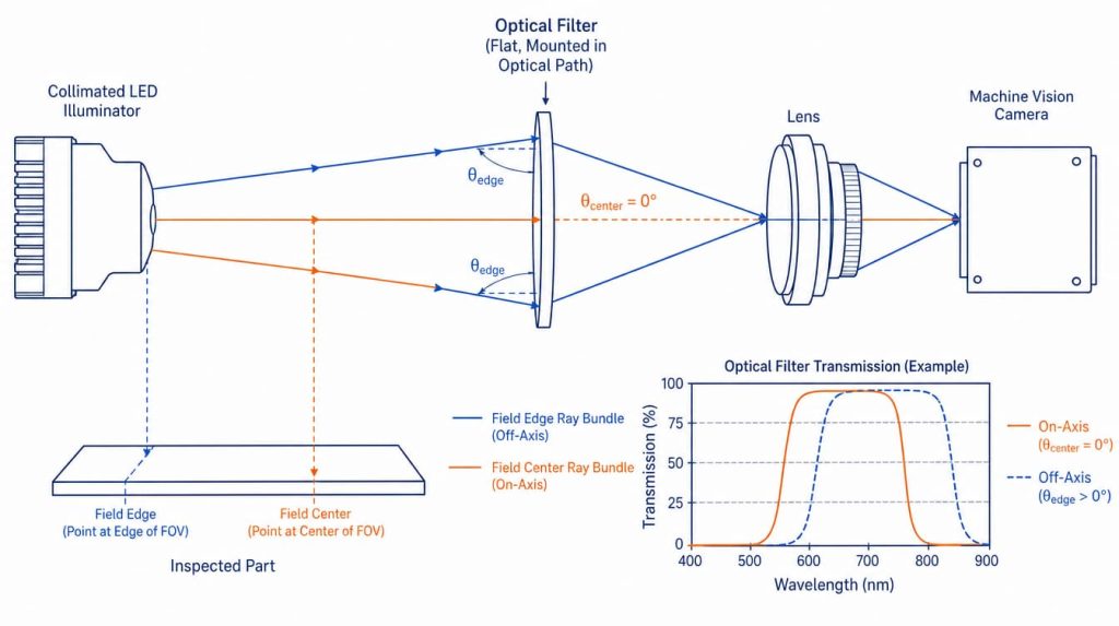
To choose an optical filter for machine vision, start from the illumination spectrum rather than the filter catalog. Match the filter passband to the light your system actually uses, then verify that the passband still lines up once you account for the range of angles striking the filter in your lens geometry. Blocking depth, coating construction, thickness, and mount all follow from those two decisions.
Most vision filter failures are not manufacturing defects. They are specification errors: a passband that was correct on the bench at normal incidence and wrong at the edge of a wide-angle field, or blocking that was adequate against room light and inadequate against a nearby heat lamp.
What problem is the filter actually solving?
Filters in a vision system do one of four things. Identify which one you need before you look at wavelengths.
| Goal | Filter type | What it does |
|---|---|---|
| Reject ambient light, keep only your illuminator | Bandpass | Transmits a defined band, blocks everything else across the sensor’s response range |
| Remove near-infrared (NIR) contamination from a color image | IR-cut (shortpass) | Blocks beyond roughly 650 to 700 nm so silicon NIR sensitivity does not distort color |
| Image only in NIR, ignore visible scene content | Longpass or NIR bandpass | Cuts on above the visible, or isolates 850 nm or 940 nm illumination |
| Suppress specular glare or stress birefringence | Linear polarizer, often crossed with a polarized source | Attenuates one polarization state; not a spectral filter |
| Reduce flux without changing color balance | Neutral density (ND) | Flat attenuation across the band, used when the sensor saturates |
A bandpass filter and an IR-cut filter sit in the same place in the optical stack and look identical, but their transmission curves are opposites. Installing the wrong one is a common and very confusing failure: the image goes dark and the illuminator gets blamed.
Match the passband to the source, not the nominal wavelength
Light-emitting diode (LED) illuminators are binned, not calibrated. A part sold as 660 nm can have a peak emission anywhere within roughly plus or minus 10 nm depending on the bin, and the peak drifts with junction temperature. NIR gallium arsenide emitters drift on the order of a few tenths of a nanometer per degree Celsius; indium gallium nitride blue and green emitters drift far less. Take both numbers from the illuminator datasheet rather than assuming.
Three quantities define the passband on a filter datasheet:
- CWL (center wavelength): the midpoint between the two 50 percent transmission points.
- FWHM (full width at half maximum): the passband width measured at those same 50 percent points. A filter specified as CWL 850 nm, FWHM 40 nm passes roughly 830 to 870 nm above 50 percent transmission.
- Peak or average transmission: how much of the in-band light survives. Modern hard-coated dielectric filters commonly reach 90 percent or better in the passband; verify per part, since transmission drops as the design gets narrower or the blocking requirement gets deeper.
The FWHM must cover the LED bin tolerance, the thermal drift, and the angular shift described below, with margin. A passband that is exactly as wide as the source emission line will clip the source as soon as anything moves.
Angle of incidence is the parameter engineers underestimate
Interference filters are thin-film resonant structures. Light arriving off normal traverses a shorter optical path through each layer, so the passband shifts toward shorter wavelengths. The standard approximation is:
λ(θ) = λ₀ × √(1 − sin²θ / n*²)
where λ₀ is the center wavelength at normal incidence, θ is the angle of incidence (AOI) in air, and n* is the effective index of the coating stack. The effective index is not the substrate index. For typical dielectric designs it falls somewhere between about 1.45 and 2.0, and higher-index stacks such as tantalum pentoxide and silicon dioxide sit at the upper end of that range. Suppliers publish n* for their designs, and it is worth asking for it.
The consequence at 850 nm:
| AOI | Shift with n* = 1.45 | Shift with n* = 1.85 |
|---|---|---|
| 5° | 1.5 nm | 0.9 nm |
| 10° | 6.1 nm | 3.8 nm |
| 15° | 13.7 nm | 8.4 nm |
| 20° | 24.0 nm | 14.7 nm |
| 25° | 36.9 nm | 22.5 nm |
Two geometries matter, and they are different:
Filter mounted in front of the lens. The filter sees the full field angle. A lens covering a 60 degree horizontal field presents rays at roughly 30 degrees AOI at the field edge. With a 20 nm FWHM filter, the corners fall out of band entirely and the image shows a dark ring that looks like severe vignetting but is spectral in origin. This is the single most common bandpass failure in short-focal-length vision setups.
Filter mounted between the lens and the sensor. The filter sees the image-space cone, which is set by the f-number. The half-angle is approximately arcsin(1/2N): about 3.6 degrees at f/8, 7.2 degrees at f/4, 14.5 degrees at f/2, and 21 degrees at f/1.4. Because the cone contains a range of angles rather than a single one, the passband both shifts and broadens, and a useful first approximation for the net center shift is roughly half of the value the formula gives for the full cone half-angle. Fast lenses and narrow filters do not combine well.
Two mitigations exist. Choose a wider FWHM with enough margin to absorb the shift, or specify a reduced-angle-shift design with a higher effective index. The second option costs more and becomes less effective at both extremes, for filters wider than roughly 3 percent bandwidth and for very narrow ones under about 1 percent.
How deep does the blocking need to be?
Blocking is quoted as optical density (OD), where OD = −log₁₀(T). OD 4 means one part in 10,000 is transmitted, OD 6 one part in a million. Two things are specified together, and both matter:
- Blocking level across the rejection band
- Blocking range, meaning the wavelength interval over which that level is guaranteed
A filter blocked to OD 4 from 200 to 1100 nm and a filter blocked to OD 4 from 400 to 900 nm are very different parts in a system using a silicon sensor, which retains meaningful quantum efficiency out past 1000 nm. Leakage outside the stated blocking range is a real defect mode: sunlight through a skylight or a nearby infrared heater produces a background that the specification never promised to suppress.
As a working guide, OD 3 to OD 4 handles ordinary factory lighting. OD 5 to OD 6 is what fluorescence, low-signal, or strong-ambient applications need, and it costs both money and in-band transmission. Do not specify OD 6 reflexively; every additional layer in the blocking stack adds absorption, scatter, and price.
Coating and construction trade-offs
| Construction | Typical transmission | Angle shift | Durability | Best for |
|---|---|---|---|---|
| Hard-coated sputtered dielectric | High, commonly above 90 percent | Follows the n* formula, improved with high-index designs | Excellent, cleanable, no delamination in humid plants | Almost all industrial vision |
| Evaporated soft coating | Moderate to high | Similar | Poor, hygroscopic, needs sealing | Legacy or low-cost designs only |
| Absorbing glass (SCHOTT RG, BG, KG series and equivalents) | Wavelength dependent | None, absorption does not shift with angle | Excellent | Wide-angle lenses, coarse cut-on requirements |
| Hybrid: dielectric plus absorbing substrate | High in band | Reduced apparent shift at the edges | Excellent | Wide-field systems needing both a defined band and angle stability |
The hybrid construction deserves attention in machine vision specifically. Because the absorbing component does not shift with angle, it can hold the far side of the blocking even when the interference component has walked away from its nominal position at the field edge. This is the standard answer to the dark-corner problem on lenses of 12 mm focal length and shorter. Suppliers such as GIAI Photonics list bandpass, longpass, shortpass, notch, and dichroic filters as separate catalog families, and hybrid construction is generally something to raise explicitly during specification rather than assume from a part number.
Mechanical and optical quality parameters
These get skipped in requests for quotation and then cause problems at integration.
Clear aperture. The specification guarantees performance only inside the clear aperture, which is smaller than the physical diameter. It must cover the lens image circle at the filter plane. A filter that meets specification across 90 percent of its diameter, mounted in a ring that masks part of the remaining edge, can still clip a wide field.
Thickness and focus shift. Inserting a plane parallel plate into a converging beam moves focus back by approximately t(n−1)/n, which is about one third of the plate thickness for common glasses near n = 1.5. A 2 mm filter behind the lens moves best focus roughly 0.67 mm. In a fixed C-mount stack with no refocus travel, that is enough to lose the image entirely. Either design the back focal distance around the filter or mount in front of the lens.
Surface quality and surface figure. Scratch-dig is normally called out to MIL-PRF-13830B, with 60-40 adequate for a filter well away from an image plane and 40-20 or tighter when it sits close to the sensor, where defects begin to image. ISO 10110-7 is the equivalent international convention and uses a different notation, so state which standard you are quoting. Transmitted wavefront distortion matters more than the figure of a single surface for a filter in a converging beam; ask for the transmitted wavefront specification if the system is diffraction-limited or is doing sub-pixel metrology.
Wedge and parallelism. A wedged filter deviates the beam and displaces the image laterally. In a gauging application with sub-pixel measurement, an unspecified wedge shows up as a fixed offset that survives calibration until someone swaps the filter.
Environmental and compliance items. Operating temperature range, adhesion and humidity per the relevant coating durability tests, and RoHS status if the assembly ships into the EU.
Common specification mistakes
- Specifying FWHM from the LED nominal wavelength alone. The bin tolerance, thermal drift, and angle shift stack. Budget all three before narrowing the band.
- Using a narrow filter in front of a wide-angle lens. The field edge shifts out of band. Move the filter behind the lens, widen the passband, or switch to a hybrid or absorbing design.
- Ignoring the blocking range endpoints. Blocking to 900 nm on a silicon sensor leaves a window open from 900 to about 1100 nm.
- Forgetting the focus shift from a rear-mounted filter. Roughly one third of the glass thickness, and often larger than the available back-focus adjustment.
- Comparing filters on peak transmission only. Peak transmission at the exact CWL says nothing about what the filter does at the source’s actual emission peak once temperature and angle are included. Compare the integrated transmission over the source spectrum.
- Cleaning a soft-coated filter with solvent. If the coating is not sputtered, aggressive cleaning removes it. Confirm the coating type before writing the maintenance procedure.
How to choose, in order
- Record the illuminator’s peak wavelength, spectral width, bin tolerance, and thermal coefficient from its datasheet.
- Decide where the filter goes, in front of the lens or behind it, and calculate the worst-case AOI for that position.
- Compute the angular shift at that AOI using the formula above and the supplier’s effective index.
- Set FWHM to cover source width, bin tolerance, thermal drift, and angular shift, with margin. Stop there. Any narrower buys ambient rejection you probably do not need at the cost of signal you do.
- Set the blocking level and range against the actual ambient environment and the sensor’s full response range, not the visible band.
- Check clear aperture against the image circle, and thickness against available back focus.
- Specify surface quality, wedge, and coating durability explicitly.
- Test with samples under real production lighting before releasing the design. Filters are inexpensive relative to illumination hardware, which makes empirical testing the cheapest step in the process.
FAQ
Should the filter go in front of the lens or behind it? In front is mechanically simpler and keeps the back focal distance untouched, but the filter then sees the full field angle, which is the worse case for an interference filter. Behind the lens the filter sees only the f-number cone, which is usually much narrower, at the cost of a focus shift of roughly one third of the glass thickness.
Is a narrower FWHM always better for ambient rejection? No. Narrowing the passband improves ambient rejection but reduces peak transmission, increases cost, and shrinks the tolerance available for LED binning, thermal drift, and angle shift. The correct FWHM is the narrowest one that still contains the source under all operating conditions with margin, not the narrowest one available.
What OD do I need for a factory with normal overhead lighting? OD 3 to OD 4 across the sensor’s full response range is usually sufficient for general-purpose inspection under fluorescent or LED overhead lighting. Move to OD 5 or OD 6 when the signal is weak relative to ambient, as in fluorescence imaging, or when direct sunlight or infrared heaters reach the scene.
Why does my image have dark corners after adding a bandpass filter? Almost certainly angular shift. At the edge of a wide field the passband has moved to shorter wavelengths and no longer overlaps the illumination. Check the field angle at the corner, put it into the shift formula, and compare the result against your FWHM. Widening the passband or relocating the filter behind the lens fixes it.
Does temperature move the filter passband? Yes, though usually far less than it moves the LED. Interference coatings shift toward longer wavelengths as temperature rises, with a coefficient that depends on the coating design and materials. In most vision systems the source drift dominates, but for narrow passbands in uncontrolled environments both should be included in the tolerance budget.
Can one filter serve both visible color imaging and NIR inspection? A dual-band filter transmits a visible band and an NIR band while blocking between them, which supports day and night operation without a mechanical switcher. The compromise is that color rendering in the visible band is less accurate than with a dedicated IR-cut filter, and out-of-band rejection between the two windows is harder to push deep.
Once the passband, blocking, and mechanical envelope are settled, the remaining work is sourcing, and the relevant categories are bandpass, narrow bandpass, longpass and shortpass, and infrared filters, all of which GIAI Photonics supplies alongside custom optical coatings for non-catalog wavelengths.
