
Technical Resources
How Substrate Material Affects Optical Coating Performance
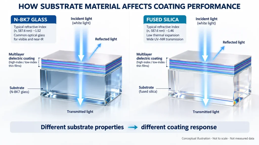
Two optical windows may use the same nominal anti-reflection coating design, yet deliver different optical results. One may achieve the expected reflectance, while the other shows higher residual reflection, increased scattering, or reduced stability after temperature cycling.
The difference may not originate in the coating materials alone. It may begin with the substrate underneath them.
Substrate material affects optical coating performance through refractive index, spectral absorption, thermal expansion, mechanical properties, surface condition, and compatibility with the deposition process. These factors determine how the coating interacts with light, how strongly it adheres, and how reliably the finished component performs under its intended operating conditions.
For optical engineers, substrate selection is therefore part of coating design rather than a separate purchasing decision.
1. Refractive Index Changes the Optical Response of a Coating
The refractive index of the substrate is one of the most direct factors affecting coating performance.
Whenever light encounters a boundary between materials with different refractive indices, part of the incident light is reflected. For an uncoated, non-absorbing interface at normal incidence, the Fresnel reflectance is:
[
R=\left(\frac{n_s-n_0}{n_s+n_0}\right)^2
]
Where:
- (R) is the power reflectance of one interface.
- (n_s) is the substrate refractive index.
- (n_0) is the refractive index of the incident medium, approximately 1 for air.
For example, at approximately 587.6 nm and normal incidence, an uncoated N-BK7 surface reflects about 4.2% of incident light, while fused silica reflects approximately 3.5%. These values are calculated for a single air–substrate interface, not measured specifications of finished coated components.
Although the difference may appear small, it changes the starting conditions for an anti-reflection coating design.
A single-layer AR coating works through interference between reflections from its interfaces. For an ideal quarter-wave layer at normal incidence, the refractive index required for zero reflection is approximately:
[
n_c=\sqrt{n_0n_s}
]
This relationship illustrates why an identical coating layer does not necessarily produce identical residual reflectance on different substrates.
For multilayer coatings, the relationship becomes more complex. The substrate refractive index influences the optical boundary conditions and must be considered alongside the refractive indices and thicknesses of the deposited layers.
Engineering implication: When changing from BK7 to fused silica, sapphire, or another optical material, an existing coating design should be re-evaluated instead of assuming its original spectral performance will remain unchanged.
This consideration applies to AR coatings, dielectric mirrors, bandpass filters, dichroic coatings, and beamsplitters.
2. Substrate Transmission Limits the Final Optical Performance
An optical coating can control reflection, transmission, or wavelength-selective filtering, but it cannot eliminate the intrinsic absorption of the substrate.
Every optical material has a wavelength-dependent transmission range. The useful range depends on its composition, impurities, material grade, thickness, and operating conditions.
For example, N-BK7 and many other optical glasses are commonly used for visible and selected near-infrared applications. Fused silica is often considered where ultraviolet transmission, low thermal expansion, or laser applications are important, provided the appropriate grade is selected.
Silicon and germanium are relevant to certain infrared optical systems, but they cannot be treated as interchangeable with visible-light optical glass.
Consider a hypothetical infrared filter whose coating is designed for high transmission at a particular wavelength. If the selected substrate strongly absorbs light at that wavelength, the completed filter cannot achieve the same high transmission as the coating design alone might suggest.
The problem becomes more significant as substrate thickness increases because bulk absorption accumulates with optical path length.
For a homogeneous material, the absorption-related internal transmission can be approximated using the Beer–Lambert relationship:
[
T_{\mathrm{internal}}=e^{-\alpha d}
]
Here, (\alpha) is the absorption coefficient at the specified wavelength, and (d) is the path length through the material. This expression describes bulk absorption; surface reflections and coating interference must be evaluated separately when calculating total component transmission.
Engineering implication: Check the substrate’s spectral transmission at the actual operating wavelength and specified thickness before finalizing the coating design.
3. Thermal Expansion Mismatch Can Affect Coating Stress and Durability
Optical coatings commonly consist of thin layers deposited on a much thicker substrate. These layers and the substrate may expand or contract at different rates as temperature changes.
The coefficient of thermal expansion (CTE) describes how a material’s dimensions respond to temperature.
When the coating and substrate have different thermal expansion coefficients, a temperature change can introduce additional mechanical stress at and around their interface.
Depending on the film system, deposition conditions, temperature history, and component geometry, excessive stress may contribute to cracking, delamination, bending, or changes in optical figure.
For comparison, typical room-temperature thermal expansion coefficients for two widely used optical materials are approximately:
| Material | Representative CTE |
|---|---|
| N-BK7 | 7.1 × 10⁻⁶/K |
| Fused silica | 0.5–0.6 × 10⁻⁶/K |
These are representative material properties, not finished-coating reliability results. Actual values depend on material grade and temperature range.
Fused silica has substantially lower thermal expansion than N-BK7. This can be advantageous in systems where dimensional stability is important.
However, low substrate expansion does not automatically mean low coating stress. A coating system developed around one substrate may have a greater expansion mismatch when deposited on another.
Residual stress also depends on factors including coating density, elastic properties, deposition temperature, and film thickness.
Thin windows and large-area coated optics deserve particular attention because coating stress can influence surface deformation and transmitted or reflected wavefront quality.
Engineering implication: Substrate selection, film stress, operating temperature, component thickness, and mounting constraints should be reviewed together.
4. Surface Quality Influences Scattering, Adhesion, and Coating Defects
Even when the substrate material is optically suitable, its surface preparation can determine whether the coating performs as intended.
Optical polishing is not simply a matter of making the substrate look smooth. The surface may contain microroughness, polishing residue, subsurface damage, fine scratches, or contamination that is difficult to identify through ordinary visual inspection.
These defects can affect coating performance in several ways.
Surface microroughness and structural irregularities can increase unwanted scattering. Residual contamination may interfere with coating adhesion or introduce localized absorption. Subsurface defects can become particularly important in laser applications.
The condition of the substrate–coating interface is therefore a critical part of the finished optical component.
Research published through Optica has demonstrated that substrate surface condition and cleaning influence coating adhesion, scattering sites, and laser damage behavior.
For high-power optical systems, the consequences can be especially significant. Localized absorbing defects may create regions where optical energy is converted into heat, potentially initiating damage.
A coating that performs well on a properly polished and cleaned substrate may not achieve the same result on a substrate with residual polishing compounds or surface damage.
Engineering implication: Surface roughness, surface imperfections, polishing quality, and cleaning requirements should be defined according to the coating function and application, rather than relying exclusively on visual appearance.
5. Substrate Chemistry and Mechanical Properties Affect Manufacturing Compatibility
Substrates differ not only in optical properties but also in hardness, chemical durability, thermal conductivity, and sensitivity to processing.
These characteristics can influence how a component is polished, cleaned, handled, and coated.
For example, sapphire offers high hardness and useful thermal properties, making it relevant to demanding optical windows. However, sapphire is also birefringent, and its crystal orientation may matter in polarization-sensitive applications.
Fused silica offers a different combination of low thermal expansion and optical transmission properties. Its response to a deposition process is not necessarily the same as that of sapphire or conventional optical glass.
Some infrared materials require additional attention to surface preparation, temperature exposure, and handling.
The cleaning procedure itself must also be compatible with the material. A cleaning chemistry suitable for one substrate may alter the surface condition of another.
This is important because damage introduced before deposition cannot always be corrected by applying a more sophisticated coating.
Engineering implication: A coating process should be qualified for the actual substrate, including its grade, surface preparation, geometry, and relevant temperature limitations.
6. Comparing Common Optical Substrates for Coating Applications
The following table summarizes material characteristics that engineers commonly consider when selecting substrates for coated optical components.
| Substrate | Relevant characteristics | Coating considerations |
|---|---|---|
| N-BK7 | Common visible and near-IR optical glass with well-characterized optical properties | Refractive index, thermal expansion, surface finish, and process compatibility |
| Fused silica | Low thermal expansion; suitable grades offer useful UV transmission | Coating stress mismatch, polishing quality, UV absorption, and laser-related requirements |
| B270 | Optical glass used in various visible-light components | Glass grade, surface preparation, thermal behavior, and coating design |
| Sapphire | High hardness, good thermal conductivity, and birefringence | Crystal orientation, residual reflectance, stress, and polarization |
| Silicon | High refractive index; useful for selected infrared applications | Wavelength-dependent absorption, surface reflection, and temperature |
| Germanium | High refractive index; used in infrared optical systems | Strong uncoated surface reflection, temperature-dependent optical behavior, and coating design |
| ZnSe | Infrared-transmitting material used in selected optical systems | Surface handling, material absorption, coating compatibility, and application conditions |
No substrate is universally superior.
For a visible-light imaging window, a conventional optical glass may be appropriate. For a UV optical system, the material grade and ultraviolet transmission become more important. For a thermal imaging component, the relevant infrared transmission and temperature behavior may dominate the selection.
The best material is the one that satisfies the full optical, mechanical, environmental, and manufacturing specification.
7. Why Identical Coatings May Perform Differently on Different Substrates
Consider an engineering comparison involving two optical windows intended to receive an AR coating for the same wavelength.
Window A is manufactured from N-BK7, while Window B uses fused silica.
Both have the same nominal dimensions, but their refractive indices and thermal expansion coefficients differ.
If an identical single-layer coating is applied to both windows, their residual reflection can differ because the optical boundary conditions are different.
If the coating process involves elevated substrate temperatures, the two windows may also develop different stress states during processing and cooling.
If their polishing and cleaning histories differ, additional variations in scattering, adhesion, or defect behavior may appear.
This example illustrates why simply copying a coating recipe from one substrate to another does not establish equivalent performance.
In practice, the coating design and manufacturing process may need to be adjusted to accommodate the new material.
The same principle applies when moving between different optical glass grades, infrared materials, or crystalline substrates.
8. Substrate Selection for High-Power Laser Coatings
In laser systems, coating performance must be evaluated beyond nominal transmission or reflection.
Optical absorption, contamination, defects, thermal conductivity, thermal expansion, and coating stress can all influence how the coated component responds to laser irradiation.
High-power continuous-wave and pulsed laser systems may also have very different failure mechanisms.
For example, a substrate with low bulk absorption at the operating wavelength can help reduce heat generation within the material. However, the coating layers, interfaces, and surface contaminants may still absorb energy.
Thermally induced wavefront deformation can also become significant in precision laser systems, even before permanent damage occurs.
Research on coated optical components shows that material selection and thermal management can influence these deformations.
A suitable substrate alone does not establish a laser-induced damage threshold (LIDT). LIDT depends on the complete coated optic, irradiation conditions, test procedure, and damage criterion.
When a laser application requires LIDT verification, the wavelength, pulse duration or continuous-wave operating condition, beam size, incidence angle, and relevant test conditions should be defined.
9. How to Specify the Substrate and Coating Together
A coating specification should describe the finished optical component, rather than only the desired film type.
For a custom optical window, filter, mirror, or coated lens, useful engineering information includes substrate designation and grade, thickness, dimensions, optical surface requirements, operating wavelength, and the coating function.
The angle of incidence is particularly important for interference coatings because spectral response can shift with angle. Polarization and angular spread may also need to be specified.
When environmental durability is important, define the expected operating temperature, humidity exposure, cleaning conditions, and relevant acceptance requirements.
A coating described only as “AR coating, high transmission” is often insufficient for engineering evaluation.
A more useful requirement identifies the optical performance to be achieved over a defined wavelength range and at a defined incidence condition, together with the substrate and inspection criteria.
The finished component can then be evaluated against those requirements.
10. How GIAI Evaluates Substrate and Coating Requirements
At GIAI Photonics, substrate selection and optical coating requirements are considered together during custom optical project evaluation.
GIAI’s publicly described material scope includes BK7, fused silica, B270, sapphire, silicon, germanium, ZnSe, MgF2, and other optical glass types.
The company supports project-specific optical fabrication and coating work for optical filters, lenses, windows, mirrors, prisms, and related components.
According to its manufacturing capabilities, coating requirements are reviewed in relation to material selection, component geometry, wavelength, transmission or reflection requirements, angle of incidence, and other relevant conditions.
The appropriate manufacturing route depends on the particular drawing and specifications. Material availability or inclusion in a general manufacturing reference does not establish that every dimension, tolerance, coating specification, or environmental requirement is achievable.
For coated filters and other wavelength-selective optics, quality assurance should include verification of the specified optical characteristics under agreed inspection conditions.
Engineers developing custom components can submit their substrate requirements, drawings, optical specifications, and operating conditions through the GIAI contact page for project-level review.
Frequently Asked Questions
Does the substrate material affect AR coating performance?
Yes. The substrate refractive index determines the reflection characteristics of the uncoated interface and influences the optical design of the AR coating. Substrate absorption, surface condition, and thermal behavior can also affect the finished component.
Can the same optical coating be used on BK7 and fused silica?
An identical coating structure can be deposited on different materials in some circumstances, but equivalent optical performance and reliability should not be assumed. The coating design and manufacturing conditions must be evaluated for each substrate.
Why can coatings crack or peel after temperature cycling?
Temperature changes can generate stress when the substrate and deposited layers expand or contract differently. Residual film stress, adhesion, surface preparation, component geometry, and processing history can also contribute to failure.
Is fused silica always better than BK7 for optical coatings?
No. Fused silica has advantages for certain UV, thermal-stability, and laser applications, but the most suitable substrate depends on wavelength, optical function, coating design, mechanical requirements, operating conditions, and cost.
Conclusion
Substrate material is an active part of optical coating performance, not merely a mechanical support for the deposited layers.
Refractive index affects reflection and interference behavior. Bulk absorption limits usable transmission. Thermal expansion and mechanical properties influence stress and stability, while surface preparation affects scattering, adhesion, and defect formation.
For reliable optical component design, the substrate, coating architecture, manufacturing process, and inspection requirements should be specified as one integrated system.
Additional engineering information is available through GIAI’s Filters & Coatings technical resources and Optical Materials & Infrared resources.
Technical References
Society of Vacuum Coaters — Procedure for Designing Optical Coatings to Control Stress.
Optica Publishing Group — Polished Substrate Surface and Cleaning Study for Coated Optic Quality.
Optica Publishing Group — Influence of Cleaning Process on the Laser-Induced Damage Threshold of Substrates.
SCHOTT — N-BK7 Optical Glass Datasheet.