
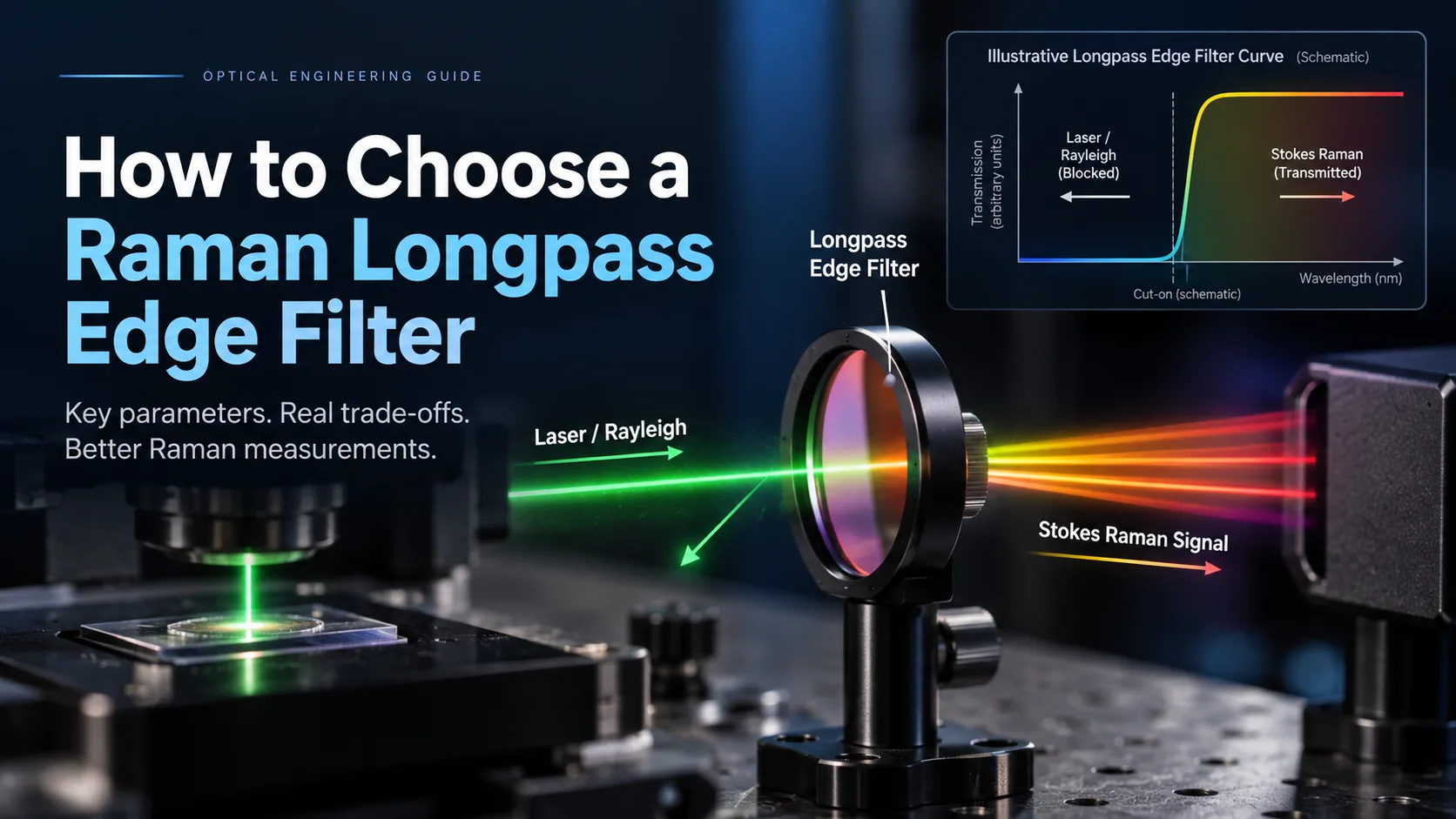
Choosing a Raman longpass edge filter should start with two numbers: the excitation laser wavelength and the lowest Stokes Raman shift you need to measure.
The nominal cut-on wavelength alone is not enough.
A useful Raman edge filter must simultaneously provide strong rejection at the laser line and transition into high transmission before the Raman signal of interest. That performance must also remain acceptable at the actual angle of incidence, beam cone, polarization state and operating conditions inside the instrument.
This is why two filters both described as a “532 nm Raman longpass filter” can produce very different low-wavenumber performance.
What Does a Raman Longpass Edge Filter Actually Do?
In Stokes Raman spectroscopy, the scattered Raman photons have longer wavelengths than the excitation laser. A longpass edge filter is therefore placed in the collection path to strongly attenuate the intense laser/Rayleigh component while transmitting the longer-wavelength Raman spectrum.
HORIBA describes edge filters as one of the main approaches used for Rayleigh rejection in Raman instruments, with the filter selected for the particular excitation wavelength.
The basic optical function is straightforward:
Laser / Rayleigh line → blocked
Stokes-shifted Raman signal → transmitted
The difficult part is the transition between those two regions.
For Raman measurements close to the laser line, a few nanometers—or even less—can determine whether the first useful Raman bands are transmitted or buried behind the filter edge.
1. Start with the Actual Excitation Laser Wavelength
Do not begin by selecting a filter from a nominal wavelength label.
Begin with the laser itself.
For example, a system described as using a 785 nm laser should still define:
- nominal excitation wavelength;
- wavelength tolerance;
- spectral linewidth;
- wavelength drift with temperature or operating condition;
- whether a laser-line cleanup filter is already present.
The rejection region of the Raman filter must cover the actual laser line, not merely the wavelength printed on the laser housing.
This becomes particularly important when the desired Raman shift is small because the usable Raman signal may lie very close to the excitation wavelength.
A laser-line cleanup filter may also be required if the laser has unwanted spectral emission outside its main line. A Raman edge filter downstream cannot necessarily distinguish this source background from a genuine Raman signal once both fall inside its transmission region.
2. Convert the Minimum Raman Shift into Wavelength
Raman spectra are normally specified in wavenumber shift, cm⁻¹, while optical filters are normally specified in wavelength.
Those two quantities must therefore be connected before defining the edge.
For Stokes scattering:
where:
- = excitation wavelength in nm;
- = Raman shift in cm⁻¹;
- = Raman wavelength in nm.
HORIBA gives the equivalent Raman-shift relationship between excitation wavelength, Raman wavelength and wavenumber.
Consider two common excitation wavelengths:
| Excitation | Raman shift | Raman wavelength | Separation from laser |
|---|---|---|---|
| 532 nm | 50 cm⁻¹ | ≈533.42 nm | ≈1.42 nm |
| 532 nm | 100 cm⁻¹ | ≈534.85 nm | ≈2.85 nm |
| 785 nm | 50 cm⁻¹ | ≈788.09 nm | ≈3.09 nm |
| 785 nm | 100 cm⁻¹ | ≈791.21 nm | ≈6.21 nm |
This illustrates an important specification point:
a given Raman shift in cm⁻¹ does not correspond to the same wavelength separation at different excitation wavelengths.
Therefore, specifying only something like “100 cm⁻¹ edge” without defining the excitation wavelength is incomplete.
3. Specify the Lowest Raman Shift You Need to Detect
This is often the most important selection parameter.
Suppose the application only requires Raman features above 300 cm⁻¹. The filter transition does not need to approach the laser as closely as it would for an application trying to measure down to 50 or 100 cm⁻¹.
A steeper edge can recover Raman information closer to the excitation wavelength, but steepness should not be specified simply as “as steep as possible.”
Instead, define two practical spectral requirements:
At the laser wavelength:
How much rejection is required?
At the lowest useful Raman wavelength:
How much transmission is required?
This is more meaningful than requesting only a nominal cut-on wavelength.
For low-wavenumber Raman measurements, edge steepness becomes especially important because the Raman signal approaches the intense Rayleigh line. Raman-oriented edge filters are specifically designed around this requirement.
4. Do Not Confuse Cut-On Wavelength with Transition Performance
The term cut-on wavelength often refers to a particular transmission level, commonly around the midpoint of an edge.
But that single point does not tell you how rapidly the filter moves from deep blocking to high transmission.
For Raman spectroscopy, a better specification may define something such as:
- minimum OD at the excitation wavelength;
- maximum allowed transmission in the laser blocking region;
- minimum transmission beginning at the required Raman shift;
- permitted transition interval between these regions.
Two longpass filters can have the same nominal cut-on wavelength while having very different transition slopes.
The filter with the better-positioned and steeper transition may allow significantly lower Raman shifts to be detected.
5. Define Laser-Line Blocking by OD—and Define Where It Applies
Blocking is normally expressed as optical density:
where is fractional transmission.
For example:
- OD4 corresponds to transmission;
- OD6 corresponds to transmission.
High-rejection Raman systems often use OD6-class or greater blocking around the laser line, particularly when attempting low-wavenumber measurements. That should not, however, be treated as a universal specification for every Raman instrument. The required blocking depends on laser power, stray light, optical geometry, spectrometer rejection and detector dynamic range.
Also specify the blocking wavelength range.
“OD6 at 785 nm” and “OD6 over a defined wavelength interval surrounding 785 nm” are not equivalent requirements.
6. Check Passband Transmission Across the Raman Spectrum
After the filter passes the first useful Raman signal, it still needs to transmit the rest of the spectrum efficiently.
Do not evaluate only the transmission immediately beside the edge.
Consider:
- minimum transmission;
- average transmission;
- usable spectral range;
- detector sensitivity range;
- coating ripple;
- any additional optical elements in the collection path.
For a spectrometer collecting a broad Raman fingerprint region, unnecessary loss across the long-wavelength passband reduces the photon budget throughout the measurement.
The optimum filter therefore balances laser rejection, edge steepness and passband throughput rather than maximizing only one specification.
7. AOI and Beam Cone Can Move the Edge
Raman filters based on multilayer interference coatings are angle-sensitive.
When the angle of incidence increases, interference-filter spectral features normally shift toward shorter wavelengths.
That creates a practical problem.
A filter may show exactly the required edge position when measured at normal incidence but shift enough inside the actual instrument to change the minimum measurable Raman shift.
The specification should therefore state:
- nominal AOI;
- AOI tolerance;
- whether the beam is collimated;
- cone half-angle or numerical aperture where relevant;
- filter position in the optical path.
A converging or diverging beam contains a distribution of incidence angles rather than one AOI. That angular distribution can broaden or smear the effective spectral transition.
This is particularly relevant in compact Raman probes, microscope systems and other fast optical geometries.
8. Consider Polarization at Non-Zero AOI
At normal incidence, polarization effects may be relatively small for many designs.
At increasing AOI, however, multilayer interference filters can develop different spectral responses for s- and p-polarized light.
For a longpass edge, the two polarization states can shift by different amounts, producing what is often called polarization splitting.
If the Raman system uses:
- a polarized excitation laser;
- polarization-resolved Raman measurements;
- a significantly tilted edge filter;
then polarization should be part of the filter specification rather than left undefined.
Using filter tilt as an informal method of “tuning” the edge should also be approached carefully. The edge may shift, but polarization response and other spectral characteristics can change at the same time.
9. Include Laser Power and LIDT Requirements When Relevant
Spectral performance is not the only requirement in a laser instrument.
If appreciable laser power can reach the filter, particularly in tightly focused or pulsed systems, the design review should include:
- CW or pulsed operation;
- average power;
- peak power;
- beam diameter at the filter;
- pulse duration;
- repetition rate;
- operating wavelength;
- required laser-induced damage threshold, if applicable.
LIDT should not be copied from another coating or assumed from the substrate material. It is a system- and coating-dependent specification and should be confirmed for the actual filter design and laser conditions.
10. Check Mechanical and Optical Integration
A Raman filter also has to fit the instrument.
Relevant inputs may include:
- outer diameter or rectangular dimensions;
- thickness;
- clear aperture;
- edge treatment;
- mounting method;
- substrate;
- transmitted wavefront requirement where relevant;
- surface quality;
- environmental conditions.
For systems where the filter sits in an imaging path, substrate quality and coating stress can matter in addition to spectral performance.
The Raman filter should therefore be treated as part of the optical system—not simply as a colored piece of glass placed in front of the spectrometer.
Raman Longpass Edge Filter Selection Checklist
| Parameter | What to specify |
|---|---|
| Excitation wavelength | Nominal wavelength plus tolerance/drift |
| Raman range | Lowest required Stokes shift in cm⁻¹ |
| Laser blocking | Required OD and wavelength interval |
| Edge transition | Blocking point and required transmission point |
| Passband | Required Raman wavelength range and transmission |
| AOI | Nominal angle and tolerance |
| Beam geometry | Collimated beam or cone/NA |
| Polarization | Random, s, p or defined laser polarization |
| Laser conditions | CW/pulsed, power, beam diameter and pulse data |
| Mechanical size | Diameter/width, thickness and clear aperture |
| Environment | Temperature and other relevant operating conditions |
| Verification | Spectral measurement conditions and acceptance criteria |
When Is a Longpass Edge Filter Not the Right Choice?
A longpass Raman edge filter is primarily suited to collecting Stokes Raman scattering.
Other system architectures may require a different solution.
If both Stokes and anti-Stokes signals must be collected around the same laser line, a notch filter may be more appropriate because it rejects a narrow region around the excitation wavelength while transmitting on both sides.
If only the anti-Stokes side is required, a shortpass configuration may be considered.
GIAI has a separate technical comparison covering this design decision in more detail: Raman Edge Filter vs Notch Filter: How to Choose.
A Better Way to Specify a Raman Edge Filter
Instead of sending a supplier:
“Need a 785 nm Raman longpass filter.”
a more useful engineering request would define:
Excitation: 785 nm
Lowest required Stokes shift: 100 cm⁻¹
Required laser-line blocking: defined OD at/around 785 nm
Required passband transmission: beginning at the corresponding Raman wavelength
AOI and cone angle: defined by the instrument geometry
Polarization: specified if relevant
Laser conditions: CW/pulsed, power and beam size
Mechanical dimensions and clear aperture: defined
Inspection conditions: agreed before production
This gives the coating designer enough information to evaluate the real spectral trade-off.
It also prevents a common failure mode: selecting a filter whose catalog edge appears correct but whose transition, AOI behavior or blocking region does not match the finished Raman instrument.
Custom Raman Filter Project Review
For custom optical projects, GIAI’s controlled project guidance is to review the optical function, wavelength range, transmission and blocking requirements, substrate, geometry, coating conditions, AOI, polarization where relevant, and inspection criteria before defining the manufacturing route.
For a Raman longpass edge filter, the most useful starting information is therefore the excitation wavelength, minimum Raman shift, required blocking, Raman collection range, AOI/beam geometry and physical dimensions.
The filter should then be evaluated against the actual instrument conditions rather than selected from the cut-on wavelength alone.