
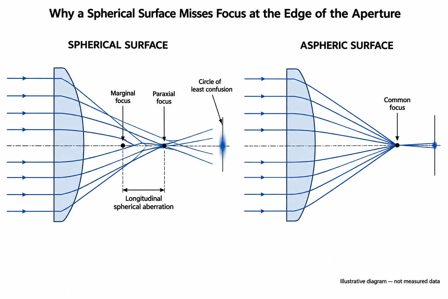
An aspheric lens reduces spherical aberration by changing its surface slope across the clear aperture, so that each annular zone refracts light by exactly the amount needed to reach one common focus. A spherical surface has the same radius everywhere, which makes the outer zones bend marginal rays too strongly and pull them to a shorter focus than paraxial rays. An aspheric profile removes that zone-to-zone focus error at a single surface, instead of balancing it against additional elements. The correction is geometrically exact only for the conjugate pair, wavelength and orientation the surface was designed for, which is why an aspheric lens used outside its design condition can perform worse than a well-chosen spherical one.
Why a spherical surface cannot bring every zone to the same focus
Refraction follows Snell’s law exactly, but first-order lens design uses the paraxial approximation sinθ ≈ θ. That approximation holds near the axis and breaks down progressively as ray height increases. On a spherical surface, the local surface normal tilts faster than linearly with radial height, so the angle of incidence of a marginal ray is larger than the paraxial model predicts and the ray is over-refracted.
For a positive singlet the result is under-correction: the marginal focus sits closer to the lens than the paraxial focus. The axial separation between them is the longitudinal spherical aberration; the resulting blur at the best focal plane is the transverse spherical aberration, and the smallest spot lies at the circle of least confusion rather than at the paraxial focus. Because the error varies smoothly with zone height, it cannot be removed by refocusing — moving the image plane only trades one zone’s sharpness for another’s.
The spherical shape is not an optical optimum. It is the shape that classical full-aperture grinding and polishing naturally generates when a tool and a workpiece move randomly against each other under uniform contact, and it is the shape that can be tested against a test plate or a spherical reference wavefront. Spherical surfaces are the manufacturing default, not the physical ideal.
How the aspheric profile removes the zone-to-zone focus error
An aspheric surface is described by a sag equation in which the base curvature is modified by a conic term and, in most designs, by higher-order polynomial terms:
z(r) = (r²/R) / [1 + √(1 − (1+k)r²/R²)] + A4r4 + A6r6 + …
Here r is radial height on the surface, R the vertex radius, k the conic constant and An the aspheric coefficients. Setting k = 0 with no polynomial terms returns a sphere. Any non-zero k flattens or steepens the surface progressively away from the vertex, which is precisely the degree of freedom a sphere lacks.
The mechanism is local and geometric. At each zone height the surface normal is re-oriented so the refracted ray aims at the paraxial focus. Rays near the axis see essentially the vertex radius and are unaffected; rays near the edge of the clear aperture see a surface that has been deliberately flattened, are refracted less strongly than a sphere would refract them, and arrive at the same axial point. The departure from the best-fit sphere needed to do this is a small fraction of the total sag, but it is the part that determines whether the marginal ray lands on focus.
The conic case: one surface, one conjugate, zero geometric spherical aberration
For a single refracting surface there is an analytic solution. If a collimated beam travelling inside a medium of refractive index n exits into air through a hyperboloidal surface with conic constant k = −n², every ray converges to the same point in the geometrical-optics limit, with no residual spherical aberration. For a common borosilicate crown at n ≈ 1.52 that corresponds to k ≈ −2.3. The same reasoning gives the parabola (k = −1) for a mirror working at infinite conjugate, and an ellipsoid when the beam is focused into the denser medium rather than out of it.
| Conic constant k | Surface generated | Typical use |
|---|---|---|
| k > 0 | Oblate ellipsoid | Rarely used alone; appears in optimised multi-term designs |
| k = 0 | Sphere | Standard fabrication and test baseline |
| −1 < k < 0 | Prolate ellipsoid | Focusing into a denser medium; finite-conjugate designs |
| k = −1 | Paraboloid | Reflective collimation and focusing at infinite conjugate |
| k < −1 | Hyperboloid | Refractive collimation or focusing at infinite conjugate; k = −n² is the stigmatic case |
This analytic result also defines the limits of the method. It holds for one conjugate pair, one wavelength and one propagation direction. Move the object from infinity to a finite distance, reverse the lens, or use it at a wavelength where the index differs appreciably, and spherical aberration reappears. Real aspheric lenses add polynomial terms precisely because they must balance performance over a waveband, a field angle range, or a conjugate other than infinity, rather than solve a single idealised case.
Why the benefit grows so quickly at low f-numbers
Spherical aberration scales steeply with aperture. For a thin lens of fixed focal length, the wavefront error from spherical aberration grows approximately with the fourth power of the clear-aperture radius, and the transverse blur diameter with the third power. Halving the f-number therefore increases the wavefront error by roughly a factor of sixteen and the geometric blur by roughly a factor of eight.
This is why the decision is driven by numerical aperture rather than by preference. At moderate f-numbers a well-oriented spherical singlet or a stock achromat is often adequate, because the residual aberration falls below the sensor pixel, the fibre core or the diffraction limit. At f/2 and faster — laser diode collimation, fibre coupling, condensers, short-working-distance focusing heads — the residual becomes the dominant error term, and no amount of lens bending removes it. Reducing the aperture is the alternative, but it costs throughput as the square of the diameter, which is usually unacceptable in exactly the applications where fast optics are specified.
What an aspheric surface does not correct
Spherical aberration is a monochromatic, on-axis aberration, and an aspheric profile addresses that term specifically. Several limitations follow directly:
- Chromatic aberration is untouched. The conic shape is independent of dispersion. A single aspheric element focusing a broadband source still shows axial colour, and for white-light or multi-line use it must be combined with an achromatic design.
- Off-axis aberrations persist. Coma, astigmatism, field curvature and distortion are field-dependent terms. A fast singlet aspherised for on-axis performance can degrade rapidly within a small field angle, so on-axis spot data alone does not describe imaging performance.
- Alignment sensitivity increases. Because the correction depends on each zone being illuminated as designed, decentration and tilt of the aspheric axis relative to the mechanical datum introduce coma that a spherical equivalent would not show. An asphere transfers part of the error budget from the lens design to the mount and assembly.
- Diffraction still sets the floor. Once geometric spherical aberration is corrected below the diffraction limit, further aspheric optimisation yields no measurable gain in spot size.
Aspheres compared with other ways of controlling spherical aberration
| Approach | How spherical aberration is reduced | On-axis residual at design conjugate | Chromatic correction | Main engineering cost |
|---|---|---|---|---|
| Plano-convex, curved face toward the collimated beam | Splits refraction between two interfaces instead of one | Reduced but clearly present at fast apertures | None | None; orientation must be controlled in assembly |
| Best-form spherical singlet | Lens bending minimises the aberration coefficient for the given conjugate | Minimised, not removed | None | Conjugate-specific shape; standard fabrication and test |
| Power split across two spherical elements | Lower ray angles at each surface | Substantially reduced | Partial, depending on glass choice | More elements, more surfaces, longer stack tolerance chain |
| Achromatic doublet | Aberration balanced between two glasses and three surfaces | Low at moderate apertures; grows at fast apertures | Axial colour corrected at two wavelengths | Cementing, glass availability, thermal behaviour of the bond |
| Conic aspheric singlet | Surface slope matched to each zone for one conjugate | Analytically zero in the geometric limit; in practice limited by form error and alignment | None | Deterministic fabrication and profile metrology; conjugate- and orientation-specific |
| Polynomial asphere (conic plus higher-order terms) | Spherical aberration balanced against field and band requirements | Designed value across the specified conditions | Only if combined with a colour-corrected design | Tightest form, slope and centration tolerances; most demanding inspection |
The table is a design-selection aid, not a ranking. An asphere that replaces three spherical elements can reduce total system length, mass and surface count, which sometimes lowers total cost even though the single element is more expensive. Equally, a stock achromat at f/4 may outperform a fast asphere used at the wrong conjugate.
Specifying an aspheric lens so the correction survives manufacturing
Aspheric surfaces cannot be generated by full-aperture lapping against a matching tool, and they cannot be verified against a test plate. Fabrication uses deterministic sub-aperture or replication processes, and verification uses profilometry or interferometric null testing. That changes what a drawing has to contain. GIAI reviews aspheric enquiries against the drawing, sample, optical requirements, substrate, geometry, coating conditions and inspection criteria before defining the manufacturing route and the applicable inspection and acceptance method.
What the drawing needs to define
- Complete surface description: vertex radius, conic constant and every aspheric coefficient, with the sag convention and the standard used. ISO 10110-12 covers aspheric surface specification; ISO 10110-5 covers surface form tolerances and ISO 10110-7 surface imperfections.
- Clear aperture over which the form tolerance applies, stated separately from the outside diameter.
- Form error as irregularity over the clear aperture, plus a slope error or mid-spatial-frequency limit where the application is sensitive to it. Peak-to-valley form error alone does not constrain the ripple left by sub-aperture tooling.
- Centration of the aspheric axis to the mechanical datum, with the datum explicitly defined. This is often the tolerance that dominates assembled performance.
- Design conjugates, orientation and wavelength or waveband, so that incoming inspection tests the surface under the condition it was designed for.
- Measurement method and acceptance criteria, including sampling and report format.
Common specification mistakes
- Using an asphere at a conjugate other than its design conjugate, then attributing the residual blur to manufacturing quality.
- Reversing the element. Orientation is part of the design, and a fast asphere fitted the wrong way round can be worse than a spherical singlet.
- Expecting an asphere to fix broadband blur that is actually axial colour.
- Tightening peak-to-valley form error while leaving slope error and test method unspecified, which raises cost without constraining the error that matters.
- Specifying an asphere where stopping down by half a stop, or choosing a colour-corrected two-element design, would meet the requirement at lower risk.
- Treating on-axis spot size as a system specification when the application uses a finite field.
For background on related surface, form and centration topics, see the Lenses & Optical Components resources, and the optical lens component family for the current lens categories.
FAQ
Does an aspheric lens always outperform a spherical one?
No. It outperforms a spherical equivalent on-axis, at its design conjugate, orientation and wavelength. Outside those conditions, and at moderate f-numbers where spherical aberration is already below the system’s resolution limit, a spherical singlet or achromat may be the better engineering choice.
Can one aspheric surface correct spherical aberration completely?
In the geometrical-optics limit a conic surface gives zero spherical aberration for a single conjugate pair and wavelength. In a real assembly the residual is set by surface form error, slope error, centration, the waveband in use and diffraction, so the practical result is a small residual rather than an exact null.
Why do aspheric lenses have polynomial coefficients if a conic already solves the problem?
Because most designs are not the idealised single-conjugate monochromatic case. Higher-order terms let the designer balance spherical aberration against field aberrations, a finite conjugate, a waveband, or a constraint on element thickness and diameter.
Will an aspheric lens fix colour fringing?
No. Chromatic aberration comes from dispersion in the substrate, and the surface shape does not change it. Broadband applications need a colour-corrected design, which may itself include an aspheric surface.
Which tolerance matters most on an aspheric drawing?
It depends on the application, but centration of the aspheric axis to the mechanical datum and slope error over the clear aperture are frequently more decisive than peak-to-valley form error, because they determine the coma and the mid-spatial-frequency scatter seen in the assembled system.
How is an aspheric surface inspected if a test plate cannot be used?
Through contact or non-contact profilometry, or interferometric testing against a null element or computer-generated hologram matched to the design. The method should be agreed before production, since it defines what the measured numbers on the report actually mean.
If you are evaluating an aspheric element for a fast collimation, coupling or focusing stage, send the drawing, optical specification or sample together with the design conjugates, wavelength range, substrate, clear aperture and outside diameter, aspheric coefficients and sag convention, form and slope tolerances, centration datum, coating requirement, inspection method and acceptance criteria, and expected quantity, and the custom optics review can confirm what is achievable before tooling is committed. Start a technical review.