
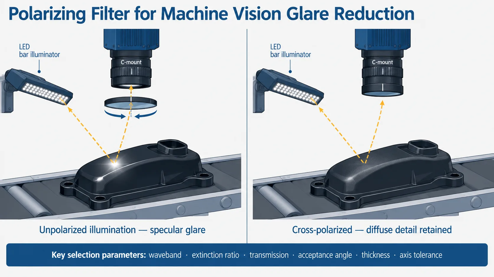
Selecting a polarizing filter for machine vision glare reduction starts with one question that has nothing to do with the filter itself: is the glare a specular reflection from a dielectric surface, or from bare metal? Dielectric glare — plastic, glass, paint, wet surfaces, film — becomes partially polarized on reflection and can often be suppressed with a single polarizer at the lens. Metallic glare stays largely unpolarized and usually requires polarized illumination plus a crossed analyzer at the camera. Only after that is settled do extinction ratio, waveband, transmission, thickness and mechanical fit become meaningful selection parameters.
What does a polarizing filter actually remove from a vision image?
Light reflected at a dielectric interface is partially polarized, with the electric field preferentially perpendicular to the plane of incidence. The effect peaks near the Brewster angle, which is roughly 56° for common optical glass (n ≈ 1.5) and roughly 53° for water. A linear polarizer oriented to block that component attenuates the specular highlight while the diffuse light returning from inside the material — which carries most of the surface texture, print and defect information — is largely depolarized and passes through at close to the normal 50% level.
Two consequences follow. Glare suppression is strongly angle-dependent: a highlight that disappears at 55° may barely change at near-normal incidence. And reflection from a metal surface behaves differently, because the complex refractive index of a conductor leaves the reflected beam only weakly polarized. Rotating a single polarizer in front of a metal part often produces disappointing results, which is the most common reason a first polarization trial fails.
Camera-side polarizer only, or polarized illumination as well?
A single polarizer at the lens works when the glare source is a dielectric reflection at a favourable angle — glossy labels, molded plastic housings, coated paper, liquid surfaces, glass covers viewed off-axis.
Cross-polarization is the alternative: a polarizing film or plate in front of the illumination, and a second polarizer at the lens rotated 90° to it. The illumination arrives linearly polarized, the specular component preserves that polarization on reflection and is blocked by the analyzer, while diffuse scattering inside the material randomizes polarization and still reaches the sensor. This method works on metal, on curved surfaces where the incidence angle varies across the field, and in coaxial or ring-light geometries where a single camera-side polarizer has no preferred axis to work against.
The cost is light. A crossed pair typically transmits only a few percent of the original flux, which pushes exposure time, gain or LED drive current up — a real constraint on a moving line.
Which specifications decide the result?
| Specification | Why it matters | What it costs you |
|---|---|---|
| Spectral range | Must cover the actual illumination band, not the visible range by default. A polarizer specified for 400–700 nm can lose most of its extinction at 850 nm or 940 nm. | Broadband types generally show lower peak extinction than narrow-band optimized types. |
| Extinction ratio (Tparallel/Tcrossed) | Sets how deeply the unwanted polarization is suppressed. Reported values range from under 100:1 for economical sheet polarizers to far higher for crystalline types. | High-extinction constructions are thicker, smaller in aperture, more expensive, and often more angle-sensitive. |
| Single transmission (unpolarized input) | Determines exposure budget. An ideal polarizer transmits 50%; real components transmit less. | Materials with the highest transmission usually do not also give the highest extinction in the same waveband. |
| Acceptance angle / cone angle | Wide-angle lenses and short working distances present a wide ray bundle. Extinction degrades toward the edge of the cone, producing uneven glare suppression across the field. | Types with the widest acceptance tend to have moderate extinction. |
| Transmitted wavefront and thickness variation | A polarizer in the imaging path is an optical element. Wedge, thickness variation and stress birefringence in laminates degrade MTF and can shift the image. | Tighter wavefront and parallelism specifications increase substrate cost and lead time. |
| Temperature and humidity rating | Polymer laminates near a high-power LED or in an outdoor enclosure can delaminate, discolour or lose extinction over time. | Glass or inorganic constructions survive more, but cost more and are usually thicker. |
| Axis marking and angular tolerance | Cross-polarization depends on the two axes being genuinely orthogonal. An unmarked part cannot be installed repeatably in production. | Tight axis tolerance is a real inspection requirement, not a free line on a drawing. |
| Aperture, outer diameter, thread and thickness | Front-of-lens filters must clear the field of view; illumination polarizers must cover the emitting area without vignetting. | Larger apertures constrain which construction types are available at all. |
Note that extinction ratio and transmission are both wavelength- and angle-dependent. A single headline number without stated test conditions is not usable for selection; ask for the curve over your working band and at your working angle.
Sheet, glass-laminated, wire-grid or crystalline?
| Construction | Typical behaviour | Where it fits in vision |
|---|---|---|
| Dichroic polymer sheet (stretched, iodine or dye based) | Absorptive, low cost, large apertures available, moderate extinction, limited thermal and UV stability | Illumination-side polarizing sheets, large-area cross-polarized lighting, laboratory trials |
| Dichroic film laminated between glass, usually AR coated | Better flatness, cleanable surfaces, better handling; still an absorptive polymer core | Front-of-lens filters in imaging paths where wavefront quality matters |
| Wire grid | Reflective rather than absorptive, broad spectral coverage, good high-temperature behaviour on glass substrates; extinction varies widely by design | NIR and IR bands, positions close to high-power illumination, applications where the rejected beam can be dumped safely |
| Birefringent crystalline (Glan type, calcite) | Highest extinction, small clear aperture, narrow acceptance angle, high cost | Metrology and polarimetric reference paths rather than production imaging |
| On-sensor micro-polarizer array cameras | Four analyzer orientations captured simultaneously; no moving filter, but reduced effective resolution and sensitivity | Scenes where the glare angle changes part to part, or where degree-of-polarization data is the measurement itself |
Reflective types remove the unwanted polarization by sending it somewhere else. In a tight enclosure that reflected beam can return as stray light, so plan where it goes.
Does the filter need to be circular rather than linear?
A circular polarizer is a linear polarizer followed by a quarter-wave retarder. For glare suppression, the linear element does the work — the retarder exists to scramble the polarization state reaching anything downstream that is itself polarization-sensitive. That matters when the optical path contains a beamsplitter, a phase-detection autofocus module, or a sensor with polarization-dependent response.
For a typical industrial camera with a fixed lens and no internal beamsplitter, a linear polarizer is simpler, thinner and usually has better extinction for the same money. If a circular type is used, it must face the correct way: linear side toward the scene, retarder side toward the sensor. Mounted backwards, it stops working as intended.
Trade-offs you cannot design away
Every polarizer discards at least half of unpolarized incoming light, and a crossed pair discards far more. On a line running at speed, that trades directly against exposure time and motion blur, or against gain and noise. Budget the light before committing to cross-polarization.
Extinction, acceptance angle and transmission pull against each other in almost every construction. Specifying the highest available extinction ratio for a wide-angle lens at short working distance often produces a worse image than a moderate-extinction part with a wider acceptance cone, because the corners behave differently from the centre.
Thickness is an optical parameter, not just mechanical. A plate inserted in a converging beam — between the lens and the sensor rather than in front of the lens — shifts the back focal distance and introduces spherical aberration and astigmatism. A filter chosen for the front of the lens is not automatically valid inside the lens barrel.
Polarization reveals what it reveals. It suppresses surface specularity; it does not remove overexposure caused by excessive illumination, blooming from a bright background, or reflections that are geometrically unavoidable. If the highlight survives a rotation test through 180°, the fix is in the lighting geometry, not in the filter.
Selection guidance by inspection case
- Print or label inspection on glossy plastic or coated paper: single camera-side linear polarizer, visible band, moderate extinction, laminated glass construction for cleanability.
- Surface defect detection on machined or coated metal: cross-polarization, with the illumination polarizer rated for the LED thermal load and the camera analyzer matched in waveband.
- Imaging through a glass cover or window: single linear polarizer, with the camera positioned so the reflection occurs near the Brewster angle where suppression is strongest.
- NIR inspection at 850 nm or 940 nm: confirm the polarizer is specified in that band; pair it with the corresponding bandpass filter so ambient light rejection and polarization control are designed together.
- Transparent film, injection-molded or laminated parts: crossed polarizers with the part between them make stress birefringence visible — here polarization is the measurement, and extinction ratio directly limits sensitivity.
- Wet or oily surfaces: single polarizer, and expect the optimum rotation angle to change as the liquid layer moves.
Common mistakes
- Reusing a photographic CPL with no published spectral or extinction data as if it were a specified optical component.
- Assuming visible-band extinction carries into the NIR. Many polymer polarizers lose most of their extinction beyond roughly 700 nm.
- Mounting a polymer laminate directly against a high-power LED housing, then attributing the gradual contrast loss to the camera.
- Leaving the transmission axis unmarked, so cross-polarization is re-tuned by hand at every changeover.
- Adding a polarizer in a converging beam without re-checking focus and aberration.
- Testing on one sample part. Surface finish, color, coating batch and temperature all change the polarization signature.
How to verify before releasing the design
Test with the production illumination, not a bench lamp. Rotate the camera-side polarizer through a full 180° and record images at fixed intervals to find the actual optimum and confirm the glare is polarization-dependent at all. Measure contrast on the defect or feature of interest, not on the highlight alone — a setting that kills the highlight but also flattens the feature is a loss. Repeat at the extremes of the field of view and at the working temperature. Then check exposure margin: if the crossed configuration only works at the camera’s maximum exposure, the design has no headroom for LED aging.
FAQ
Will a polarizing filter remove all glare in a machine vision image?
No. It suppresses the polarized component of specular reflection. Reflections from bare metal, geometrically unavoidable direct reflections and sensor saturation from overall overexposure are not solved by polarization.
How much light does cross-polarization cost?
Each polarizer removes at least half the unpolarized light, and the crossed pair removes considerably more. Exact throughput depends on the transmission and extinction of the specific parts, so evaluate it with the actual components before fixing exposure time.
Can one polarizer cover both visible and NIR inspection?
Only if it is specified over that full range. Broadband parts exist, but extinction and transmission normally vary across the band, so request data at both working wavelengths rather than assuming a single figure applies.
Linear or circular for an industrial camera?
Linear, unless something downstream in the optical path is polarization-sensitive — a beamsplitter, certain autofocus modules, or a polarization-sensitive sensor. The circular type adds a retarder and must be installed with the linear side facing the scene.
Does the polarizer belong in front of the lens or behind it?
In front, in a collimated or near-collimated region, unless the optical design specifically accounts for a plate in the converging beam. Inserting a plate between lens and sensor shifts focus and adds aberration.
What should be defined on the drawing?
Clear aperture, outer dimensions, thickness and tolerance, substrate, AR coating requirement, working waveband, extinction ratio and transmission with stated test conditions and angle, transmission axis marking with angular tolerance, operating temperature and humidity, and the acceptance criteria used at incoming inspection.
Specifying the optical path as a whole
Polarization control rarely stands alone. A vision system that uses a polarizer usually also has a bandpass or IR-cut requirement, a protective window, coating requirements on each surface, and sometimes a beamsplitter whose polarization behaviour interacts with everything upstream. Defining those together avoids a filter that performs correctly in isolation and poorly in the assembly. Background on spectral and coating parameters is collected in the filters and coatings resources, and the project route from specification to production is described under custom optics process.
For a project-level review at GIAI Photonics, send the working wavelength or spectral band, substrate preference, clear aperture and outer dimensions, thickness and parallelism requirements, coating requirements, angle of incidence or cone angle, the extinction ratio and transmission targets with the test conditions they refer to, axis marking and angular tolerance, inspection and acceptance criteria, operating environment, and expected quantity. A drawing or sample shortens the evaluation. Send the specification for technical review.