
Technical Resources
OD4 vs OD6 Optical Filter Blocking: Key Differences
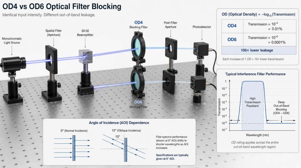
The practical difference between OD4 vs OD6 optical filter blocking is a factor of 100 in transmitted unwanted light. OD4 permits a maximum transmittance of 10-4, or 0.01%, while OD6 corresponds to 10-6, or 0.0001%. That difference can be important when a detector must separate a weak signal from a strong laser line, excitation source, ambient spectrum, or other out-of-band radiation.
However, OD6 is not automatically the better specification. Optical density has meaning only when it is tied to a wavelength range, angle of incidence, polarization state and measurement condition. In many imaging and sensing systems, OD4 provides sufficient suppression. In other systems, even OD6 at one wavelength may be inadequate because unwanted radiation is leaking elsewhere in the detector’s sensitivity range.
What Does Optical Density Mean?
Optical density, or OD, expresses transmission attenuation on a logarithmic scale. For an optical filter:
where T is transmittance expressed as a decimal fraction rather than a percentage.
The inverse relationship is:
This logarithmic definition is useful because optical filters often need to describe extremely small leakage values that would be inconvenient to compare as percentages.
| Optical Density | Fractional Transmission | Percent Transmission | Attenuation Factor |
|---|---|---|---|
| OD2 | 10-2 | 1% | 100× |
| OD3 | 10-3 | 0.1% | 1,000× |
| OD4 | 10-4 | 0.01% | 10,000× |
| OD5 | 10-5 | 0.001% | 100,000× |
| OD6 | 10-6 | 0.0001% | 1,000,000× |
Describing OD4 as 99.99% blocking and OD6 as 99.9999% blocking can make the difference appear small. For detector design, the residual transmission is usually the more useful number: OD6 leaves only one hundredth of the leakage allowed by OD4.
OD4 vs OD6 Optical Filter Blocking: Direct Comparison
| Parameter | OD4 | OD6 |
|---|---|---|
| Maximum nominal transmittance | 10-4 | 10-6 |
| Percent transmission | 0.01% | 0.0001% |
| Attenuation | 10,000× | 1,000,000× |
| Relative leakage | 100× more than OD6 | 1/100 of OD4 leakage |
| Measurement difficulty | Moderate | Significantly more demanding |
| Typical selection logic | Use when remaining background is already below the system noise or error budget | Use when OD4 leakage would remain significant relative to the required signal |
The two-OD difference is therefore substantial optically, but the improvement in final system performance is not necessarily 100×. Detector read noise, shot noise, dark current, scattering, reflections, electronic noise and in-band background may dominate after out-of-band leakage has been sufficiently reduced.
Why OD6 Does Not Automatically Produce 100× Better SNR
Consider an unwanted optical component producing 1 mW at the filter. If the simplified assumption is made that the OD applies exactly at that wavelength:
- OD4 would transmit approximately 100 nW.
- OD6 would transmit approximately 1 nW.
The optical leakage is reduced by 100×. But suppose the detector already receives 500 nW of in-band background from scattering that the filter cannot distinguish from the signal. Replacing OD4 with OD6 removes most of the out-of-band component, yet the in-band background remains.
A more useful engineering representation of detected out-of-band background is:
where Sbg(λ) is the unwanted spectral power, Tfilter(λ) is filter transmission and Rdetector(λ) is detector responsivity.
This explains why OD selection should be performed at the system level rather than from a generic application label.
When Is OD4 Blocking Usually Sufficient?
OD4 can be entirely appropriate when the calculated residual out-of-band signal is already small relative to the useful signal and the detector’s noise budget.
Examples may include:
- Machine vision systems using controlled narrowband illumination where ambient radiation is moderate.
- Imaging systems where unwanted wavelengths are substantially weaker than the desired signal.
- Sensors with limited responsivity outside the selected passband.
- Applications where optical baffling and enclosure design already suppress most stray light.
- Systems in which detector noise dominates before OD4 leakage becomes significant.
The important criterion is not whether an application is called “machine vision” or “sensing.” The criterion is how much unwanted optical power can reach the detector after multiplication by the complete filter transmission curve and detector responsivity.
When Does OD6 Become Important?
OD6 becomes more relevant when the useful optical signal is weak compared with an unwanted source or when a sensitive detector can respond strongly to very small spectral leakage.
Typical situations include:
- Separation of weak fluorescence emission from a much stronger excitation wavelength.
- Laser-based measurements where scattered laser energy is many orders of magnitude stronger than the detected signal.
- Some Raman and spectroscopy systems with very large source-to-signal ratios.
- High-sensitivity detection using detectors with broad spectral response.
- Multi-channel optical systems where leakage from one channel can contaminate another.
Even in these systems, OD6 should be specified only where necessary. A filter specified as OD6 over an unnecessarily broad spectral range may require a more complex coating design and can create additional constraints on transmission, spectral edges and verification.
Blocking Range Can Matter More Than OD4 vs OD6
An OD value without a wavelength interval is incomplete.
For example, these are fundamentally different specifications:
- OD ≥ 6 at 532 nm
- OD ≥ 6 from 520 to 540 nm
- OD ≥ 6 from 400 to 650 nm
All three contain the number OD6, but they impose very different optical requirements.
Suppose a silicon detector is responsive well beyond the visible passband. A filter might provide OD6 close to an unwanted laser wavelength yet allow significant near-infrared leakage. If the source, environment or system contains sufficient NIR radiation, that leakage can still reach the detector.
OD Is Transmission Attenuation, Not a Statement About Reflection or Absorption
Optical density describes how much light is transmitted. It does not by itself tell you what happens to the rejected optical power.
Depending on filter construction, rejected radiation may be predominantly:
- reflected by a dielectric interference coating,
- absorbed by a substrate or coating,
- or divided between reflection, absorption and small scattering losses.
This distinction can affect the surrounding system. Reflected unwanted light may create secondary stray-light paths or ghost reflections. Absorbed optical power can produce heating when incident power is high.
Therefore, a filter with OD6 transmission blocking should not automatically be described as having a particular reflectivity, absorption level or laser damage threshold. Those are separate specifications.
How Are OD4 and OD6 Verified?
Measuring high transmission through a passband and measuring extremely low transmission in a blocking band are different metrology problems.
At OD4, the transmitted signal is 10-4 of the incident level. At OD6, it is 10-6. As transmission decreases, instrument stray light, detector noise, source stability, wavelength accuracy and spectrometer dynamic range become increasingly important.
A normal transmission scan that measures the passband accurately may therefore be insufficient to prove deep blocking.
Important measurement parameters include:
- instrument stray-light level,
- available dynamic range,
- spectral bandwidth or slit width,
- wavelength step size,
- source intensity,
- detector sensitivity,
- reference-beam configuration,
- sample beam diameter and cone angle.
There is also a trade-off between measuring steep spectral edges accurately and achieving a sufficiently low noise floor. A wide spectral bandwidth may increase optical signal and improve high-OD measurement capability, but it can blur steep transitions. A narrow bandwidth improves wavelength resolution but reduces received optical power.
For this reason, an apparent flat OD6 region on a spectrum should not automatically be interpreted as the exact filter transmission. In some measurements it can represent the practical measurement floor of the test configuration.
Angle of Incidence and Polarization Must Be Specified
For interference filters, spectral performance changes with angle of incidence. Increasing AOI generally shifts interference features toward shorter wavelengths. At larger angles, s- and p-polarized light can also behave differently.
Consequently, a filter specified as OD6 at normal incidence cannot automatically be assumed to remain OD6 at 30°, 45° or over a large converging beam.
The relevant specification should define:
- nominal AOI,
- allowed angular range or cone angle,
- polarization state when relevant,
- required passband and blocking range under those conditions.
This is especially important when filters are placed in converging beams or in systems with a large field of view, because different rays may encounter different angles even when the mechanical filter itself appears to be mounted close to normal incidence.
Do Not Trade OD Against CWL, FWHM or Passband Transmission
OD describes blocking. It does not replace the other spectral specifications.
A bandpass filter still needs separate definitions for:
- CWL: the specified center wavelength.
- FWHM: the width of the passband measured between the half-maximum transmission points.
- Peak or average passband transmission: how efficiently useful light is transmitted.
- Blocking range: where unwanted light must be attenuated.
- Minimum OD: how strongly that unwanted light must be attenuated.
For example, changing from OD4 to OD6 does not inherently make the filter’s center wavelength more accurate or its FWHM narrower. These are independent requirements, although they interact during coating design.
Substrate Transmission Is Not the Same as Finished Filter Performance
The substrate and coating should also be evaluated separately.
An optical glass substrate may transmit broadly while the coating creates the required spectral blocking. Conversely, an absorptive substrate may contribute substantially to out-of-band attenuation.
A substrate transmission curve alone therefore cannot establish the OD4 or OD6 blocking performance of the finished coated filter. The complete component, including coating system, substrate, surfaces and specified operating conditions, is what matters.
A Practical Method for Choosing OD4 or OD6
-
Define the useful signal wavelength range.
Start with the source or emission spectrum that must reach the detector. -
Define the detector response.
Identify wavelengths to which the detector remains sensitive, even outside the desired passband. -
Identify unwanted optical sources.
Include illumination sidebands, ambient light, laser scatter, secondary emitters and other channels. -
Estimate allowable leakage.
Determine how much unwanted optical power can reach the detector without violating the system’s signal-to-background or measurement requirement. -
Convert that requirement to OD.
If attenuation of at least 10,000× is required, OD4 corresponds to that transmission ratio. If at least 1,000,000× is required, OD6 corresponds to that ratio. -
Define the wavelength range.
State exactly where the required OD must apply rather than writing only “OD6 blocking.” -
Add AOI and polarization conditions.
Evaluate the filter under the actual geometry of the optical system. -
Confirm that the measurement method can verify the requirement.
Deep blocking is meaningful only if the inspection method has sufficient dynamic range and controlled stray light.
Common Mistakes When Comparing OD4 and OD6 Filters
1. Comparing blocking percentages instead of leakage
99.99% and 99.9999% blocking appear almost identical as percentages. The residual transmission differs by 100×.
2. Specifying OD without a wavelength range
OD6 at one wavelength is not equivalent to OD6 over hundreds of nanometers.
3. Assuming more OD always improves the system
Once filter leakage falls below other noise sources, additional out-of-band attenuation may provide little practical benefit.
4. Ignoring angle of incidence
An interference filter measured at 0° may have different passband edges and blocking behavior when used at an oblique AOI or inside a converging beam.
5. Treating OD as reflectivity
OD describes transmitted light. It does not specify whether rejected energy is reflected or absorbed.
6. Assuming every OD6 spectrum is measured directly
Deep-blocking measurements can approach the stray-light and noise floor of the measurement system. The test method and its usable dynamic range should be understood when OD6 performance is critical.
Conclusion
The fundamental difference between OD4 vs OD6 optical filter blocking is straightforward: OD4 corresponds to 10-4 transmission, while OD6 corresponds to 10-6. Under the same wavelength and measurement conditions, OD6 therefore reduces transmitted unwanted light by another factor of 100.
The engineering decision is less simple. Required OD should be derived from the unwanted source spectrum, useful signal level, detector responsivity, blocking wavelength range, angle of incidence, polarization and system noise budget.
OD4 can be sufficient when residual out-of-band leakage is already negligible. OD6 becomes valuable when strong unwanted radiation must be separated from a weak signal. In either case, the full spectral specification and the measurement method matter more than choosing the largest OD number available.
FAQ
Is OD6 100 times better than OD4?
OD6 provides 100 times lower transmitted leakage than OD4 at the wavelength and conditions where the specification applies. OD4 corresponds to transmission of 10-4, while OD6 corresponds to 10-6. This does not mean the complete optical system will perform 100 times better. Once out-of-band leakage becomes smaller than detector noise, in-band stray light, scattering or electronic noise, increasing filter OD may produce a much smaller improvement in the final signal-to-noise ratio.
What percentage of light passes through an OD4 filter?
An optical density of 4 corresponds to 0.01% transmission, assuming the OD4 value applies at the wavelength being evaluated. In fractional form, transmission is 10-4. The value should not be interpreted as the transmission of the complete filter at every wavelength. A bandpass filter may have high transmission in its passband while providing OD4 only within specifically defined out-of-band wavelength regions.
What percentage of light passes through an OD6 filter?
OD6 corresponds to 0.0001% transmission, or a fractional transmission of 10-6. This represents attenuation by a factor of one million. The specification still needs a blocking wavelength range and operating conditions. An OD6 value around one laser wavelength does not prove that the filter provides OD6 across the detector’s entire response range, and performance can also change with angle of incidence and polarization.
Should I choose OD6 for fluorescence or laser applications?
OD6 may be appropriate when strong excitation or laser radiation must be rejected before a much weaker signal reaches the detector, but it should not be selected from the application name alone. The required OD depends on the excitation power, scattered-light level, signal strength, detector sensitivity and spectral separation. Calculate or estimate the acceptable leakage first, then specify the required minimum OD across the wavelengths where unwanted radiation can produce detector response.
Why is OD6 harder to measure than OD4?
OD6 requires measurement of transmission around one part per million, so spectrometer stray light, detector noise and available dynamic range can become comparable to the transmitted signal. Measurement settings that increase spectral resolution can also reduce optical power and raise the effective noise floor. Reliable verification therefore requires a measurement configuration suitable for deep blocking rather than assuming that a standard high-transmission spectral scan can accurately characterize both the passband and an OD6 blocking region.
