
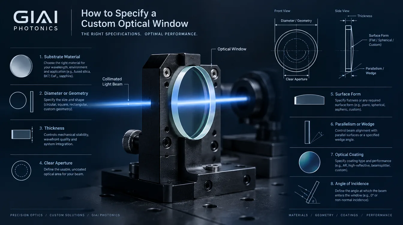
A useful custom optical window specification should define more than material and dimensions. At minimum, it should describe the operating wavelength, substrate or material grade, geometry, thickness, clear aperture, optical quality, surface imperfections, parallelism or wedge, coating performance, angle of incidence, environment, inspection conditions, and quantity.
A request such as “50 mm fused silica window with AR coating” may be enough to begin a discussion, but it is usually not enough to manufacture and inspect the final part consistently.
The reason is simple: an optical window may look like a flat piece of glass, but in the system it can affect transmission, wavefront quality, beam direction, ghost reflections, focus, environmental sealing, and mechanical reliability.
What Does an Optical Window Need to Do?
An optical window is a generally flat transmitting element used to protect, separate, or isolate part of an optical system while allowing the required light to pass. GIAI describes optical windows as components used for transmission, protection, and separation within optical systems.
Before selecting tolerances, define the window’s actual function.
A protective cover in front of an industrial camera does not necessarily need the same specification as a window inside an interferometer, a laser beam path, an infrared detector, or a pressure-sealed optical enclosure.
This function determines which specifications are critical and which would simply add manufacturing cost without improving system performance.
1. Define the Wavelength Range and Optical Function First
Start with the actual wavelength range rather than the substrate name.
For example, specify whether the window must transmit a single laser wavelength, a visible imaging band, UV radiation, near-infrared light, or a wider spectral range. If there is a minimum transmission requirement, state the wavelength interval over which it applies.
The wavelength requirement affects material selection, coating design, inspection equipment, and sometimes the appropriate material grade.
Do not write only:
AR coated optical window
A more useful specification would define the working spectral band, required transmission or reflection limit, angle of incidence, and whether the requirement applies to one surface or the assembled window.
For broadband imaging systems, also consider the spectral response of the source and detector. A coating that performs well at one nominal wavelength may not provide the same result over the entire operating band.
2. Specify the Optical Material — and the Grade When It Matters
The material should be selected against the full application rather than from wavelength transmission alone.
Important considerations include optical transmission, refractive index, thermal behavior, mechanical durability, chemical exposure, abrasion, material homogeneity, birefringence, and coating compatibility.
Typical custom-window projects may use optical glass, fused silica, sapphire, or infrared materials, but these materials are not interchangeable simply because their transmission bands overlap.
For some applications, the material description itself is incomplete unless the grade or crystal orientation is also defined. This is particularly important near a material’s spectral limits or when polarization, wavefront quality, temperature, or environmental durability matters.
For a detailed material comparison, an adjacent GIAI resource on sapphire and fused silica windows can support this stage of the selection process.
3. Define Shape, Size, Thickness, and Mechanical Interface
A custom optical window drawing should clearly define its physical boundary.
For a circular part, this normally includes outside diameter and thickness. Rectangular, square, stepped, slotted, or other non-standard windows require the relevant length, width, radii, edge features, reference surfaces, and mechanical datums.
Thickness is not only a purchasing dimension. It can affect mechanical stiffness, optical path length, weight, thermal behavior, and system integration.
For windows used across a pressure differential or large unsupported aperture, thickness should also be evaluated as part of the mechanical design. Pressure, unsupported diameter, mounting condition, temperature, material strength, and required safety margin all matter; an optical flatness specification should not be treated as a structural requirement.
Edge requirements should also be defined when relevant, including bevels, chamfers, ground edges, orientation marks, or mounting features.
4. Define the Clear Aperture Separately From the Part Size
The clear aperture is the region of the window through which the useful optical beam is expected to pass and over which specified optical performance is required.
It should not automatically be assumed to equal the full outside diameter.
For example, the mounting structure may cover the outer part of a window, allowing optical specifications to apply only to the central region. Conversely, a large scanning beam may require useful optical performance very close to the physical edge.
Clear aperture becomes especially important when specifying surface form, wavefront performance, surface imperfections, or coating uniformity.
Whenever a tolerance applies only within a particular test region, define that region explicitly.
ISO 10110-1 provides the general framework for indicating optical characteristics, tolerances, test regions, materials, dimensions, and other requirements on optical drawings. The current ISO 10110-1:2019 edition was confirmed in 2025.
5. Do Not Confuse Surface Flatness, Wavefront, and Parallelism
These parameters describe different characteristics.
| Parameter | What it controls | Why it may matter |
|---|---|---|
| Surface form / flatness | Departure of an individual polished surface from its specified planar form | Reflection quality, wavefront contribution, precision beam paths |
| Transmitted wavefront | Optical wavefront after passing through the window | Imaging, interferometry, collimated laser beams, measurement systems |
| Parallelism / wedge | Relative angle between the two surfaces | Beam deviation, alignment, ghost separation |
| Thickness | Distance between the two faces | Optical path, mechanical stiffness, focus effects and packaging |
A frequent specification mistake is to request extremely tight surface flatness while never defining transmitted wavefront performance.
If the system actually cares about the wavefront after light passes through the complete window, transmitted wavefront may be the more meaningful acceptance characteristic. Surface errors on both sides, substrate properties, and the complete transmitting element can contribute to the final result.
ISO 10110-5:2026 addresses surface-form tolerances. The current edition also makes nanometres the preferred standard unit for surface-form deviation; if fringe-spacing notation is used, the reference wavelength needs to be stated.
Wavefront deformation is addressed separately within the ISO 10110 series, including ISO 10110-14.
Should an Optical Window Always Have Very Tight Parallelism?
No.
The correct requirement depends on what the system needs.
A nearly parallel window may be appropriate where beam deviation must be minimized. In another system, an intentional wedge can help spatially separate front- and rear-surface reflections and reduce unwanted ghost overlap or etalon-type interference.
The drawing should therefore specify whether parallelism is required or whether a controlled wedge is intentional. Do not assume that “more parallel” is universally better.
6. Consider Where the Window Sits in the Beam
The same window can behave differently depending on optical-system geometry.
A window placed near normal incidence in a collimated beam may primarily need control of wavefront, wedge, transmission, and reflections.
At oblique incidence, beam displacement, polarization behavior, and coating performance become more relevant.
In a converging or diverging beam, window thickness and refractive index can affect focus and aberration. This becomes increasingly important in faster optical systems.
For this reason, an RFQ should identify the approximate window position when the geometry is optically sensitive. Providing AOI alone may not be sufficient if the beam contains a wide angular cone.
7. Specify Surface Imperfections With a Defined Standard
“Optically polished” is not an acceptance specification.
Surface imperfections matter differently depending on application. A cosmetic cover window, imaging window, high-power beam-path window, and inspection-system window can tolerate different defect levels.
The specification should therefore identify both the acceptance level and the standard used to interpret it.
ISO 10110-7:2017 covers the indication and acceptance of localized surface imperfections, scratches, edge chips, and related defects on finished transmitting and reflecting optical surfaces. It remains the current confirmed edition.
If your organization instead uses a scratch-dig convention, identify the applicable standard explicitly. An unlabeled value such as “40-20” can create ambiguity between customer and supplier.
Also avoid specifying a much tighter cosmetic requirement than the application requires. Surface-quality requirements can affect yield and manufacturing cost without necessarily improving system performance.
8. Define the Coating as an Optical Requirement, Not Just a Name
“AR coating” is usually incomplete.
A manufacturable coating specification should connect the coating with the operating conditions.
The most important inputs are typically the spectral band, transmission or reflectance target, AOI or AOI range, polarization where relevant, substrate, coated surface or surfaces, clear aperture, and operating environment.
For systems with a cone of incidence angles, communicate that angular range rather than giving only a single nominal AOI.
This matters because coating behavior is tied to the optical system, not merely to the substrate. GIAI’s manufacturing process likewise reviews wavelength range, transmission or reflection target, substrate, AOI, polarization where relevant, geometry, and inspection requirements together when evaluating coated custom optics.
9. Include Environmental and Mounting Conditions
Environmental information can change both material and coating decisions.
Relevant conditions may include temperature range, thermal cycling, humidity, vacuum, outdoor exposure, chemical contact, frequent cleaning, abrasion, pressure differential, and sealing requirements.
Mechanical mounting also matters.
If a thin window is clamped aggressively around its edge, assembly stress can alter optical performance. If an adhesive mount is used, its geometry and cure behavior may matter. If the window forms part of a sealed housing, edge dimensions and mechanical tolerances may become more critical than cosmetic surface requirements.
Do not specify the optical component independently from the way it will actually be mounted if mounting stress or environmental loading could affect its performance.
10. Define Inspection Conditions Before Production
A good specification answers not only “what should the part be?” but also “how will we decide that the part passes?”
Define the characteristics that require inspection, the test aperture, measurement wavelength, measurement orientation, AOI where relevant, and any documentation required with the shipment.
For custom optical components, GIAI’s public quality process is based on the drawing, optical specification, and project-specific acceptance criteria rather than applying one universal inspection plan to every component.
This is also reflected in GIAI’s controlled manufacturing reference: optical windows are included in the supported component scope, and projects can begin from drawings, specifications, or samples, with manufacturing and inspection routes defined at the project level.
A Practical Custom Optical Window Specification Checklist
The following table is a useful starting point for an RFQ or engineering drawing. It is not a universal specification; each field should be defined only as tightly as the application requires.
| Specification field | Information to provide |
|---|---|
| Optical function | Protection, transmission, environmental separation, laser window, imaging window, sensor window, etc. |
| Wavelength | Operating wavelength or spectral range |
| Material | Material, grade, orientation if relevant |
| Geometry | Diameter or L × W, thickness, shape and critical features |
| Dimensional tolerances | Only where functionally required |
| Clear aperture | Diameter, percentage, or defined test region |
| Surface form | Required surface-form tolerance and reference conditions |
| Transmitted wavefront | If system wavefront is performance-critical |
| Parallelism / wedge | Maximum parallelism or intentional wedge requirement |
| Surface imperfections | Acceptance level plus applicable standard |
| Coating | Spectral target, coated face(s), AOI, polarization and acceptance limits |
| Environment | Temperature, humidity, pressure, abrasion, chemicals, cleaning, vacuum, etc. |
| Mounting | Mechanical interface or relevant mounting constraints |
| Inspection | Measurement condition, acceptance method and required report |
| Quantity | Prototype, validation quantity and expected production volume |
Common Specification Mistakes
| Ambiguous requirement | Better engineering definition |
|---|---|
| “Fused silica” | State the required grade when grade affects the application |
| “AR coating” | Define spectral range, optical target, AOI and polarization if relevant |
| “λ/4 flatness” | Define what surface, aperture and reference wavelength the value applies to |
| “High surface quality” | State the acceptance level and inspection standard |
| “Parallel window” | State allowable parallelism or wedge |
| “90% transmission” | Define the wavelength range and measurement conditions |
| “Outdoor use” | Define temperature, humidity, cleaning and exposure conditions |
| “Same as sample” | Supply the sample plus dimensions and the characteristics that must be duplicated |
The goal is not to maximize the number of tight tolerances. It is to identify the tolerances that actually control system performance.
How GIAI Reviews a Custom Optical Window Project
GIAI Photonics supports custom optical windows as part of its precision optical component manufacturing scope. Public manufacturing information describes project review around the drawing or sample, wavelength, optical function, substrate, geometry, coating conditions, mechanical interfaces, and inspection criteria before the manufacturing route is defined. Processing can involve grinding, polishing, edging, coating, cleaning, and inspection as appropriate for the individual component.
This project-specific approach is important because material, thickness, surface requirements, coating, clear aperture, and inspection criteria interact. A tolerance that is straightforward for one geometry cannot automatically be treated as a universal capability for every optical window.
For technical review, send the drawing, optical specification, or sample together with the operating wavelength, substrate, dimensions, clear aperture, coating requirements, AOI, environment, inspection criteria, and expected quantity.
FAQ
What information is most important when specifying a custom optical window?
Start with optical function, wavelength range, material, dimensions, thickness, clear aperture, coating conditions, and the optical characteristics that affect system performance. Then define inspection conditions and environmental requirements. Surface flatness, transmitted wavefront, surface imperfections, and parallelism should be added according to the actual application rather than automatically tightened.
Is surface flatness the same as transmitted wavefront error?
No. Surface flatness describes an individual surface, while transmitted wavefront describes the effect on the wavefront after light passes through the complete optic. In wavefront-sensitive systems, specifying transmitted wavefront directly can be more meaningful than relying only on individual surface-form tolerances.
Does an optical window need to be perfectly parallel?
Not necessarily. Tight parallelism may be useful when beam deviation must be minimized, while intentional wedge can help separate unwanted surface reflections. The appropriate choice depends on the optical layout.
What should be included in an AR coating specification?
Define the wavelength band, required transmission or reflection performance, substrate, AOI or angular range, polarization if relevant, coated face or faces, and measurement conditions. Writing only “AR coated” leaves important engineering decisions undefined.
Should I specify every tolerance as tightly as possible?
No. Over-specification can increase processing difficulty, inspection requirements, cost, and lead time without improving system performance. Tolerances should be derived from the optical and mechanical function of the window.