
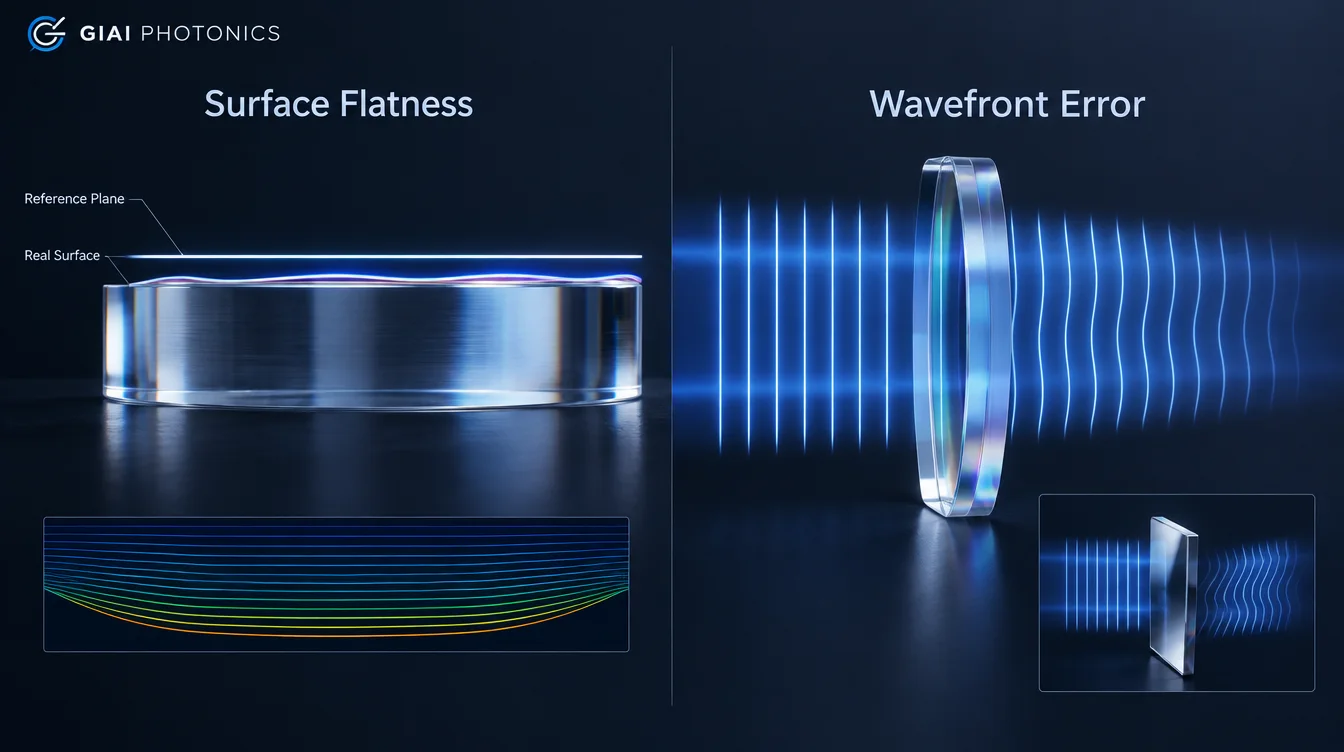
Surface flatness and wavefront error are related, but they are not interchangeable specifications.
Surface flatness describes how much a nominally flat optical surface departs from an ideal plane. Wavefront error describes how much an optical component or system changes the shape of an optical wavefront after transmission or reflection.
This distinction matters because a window can have two individually flat surfaces and still introduce transmitted wavefront error, while a mirror surface error can directly distort the reflected wavefront.
ISO drawing standards also treat surface form and wavefront deformation as separate characteristics. ISO 10110-5 covers surface form tolerances, while ISO 10110-14 addresses permissible transmitted or reflected wavefront deformation.
Surface Flatness vs Wavefront Error at a Glance
| Parameter | Surface Flatness | Wavefront Error |
|---|---|---|
| What it describes | Departure of a nominally flat surface from an ideal plane | Departure of an actual wavefront from its intended wavefront |
| What is evaluated | An optical surface | Light after transmission or reflection |
| Typical scope | One surface | A complete optic, assembly, or optical path |
| Common reporting | nm, or fractions of a wavelength under defined conventions | nm or waves, usually PV or RMS |
| Main contributors | Polishing, substrate deformation, coating stress, mounting stress | Surface form, multiple surfaces, material homogeneity, thickness variation, alignment, mounting and other optical effects |
| Especially relevant to | Mirrors, windows, flats, prisms and plano surfaces | Imaging systems, laser beam delivery, windows, filters, beamsplitters, lenses and assemblies |
| Directly interchangeable? | No | No |
The important engineering question is therefore not simply “Which number is tighter?” It is “Which physical characteristic actually controls system performance?”
What Is Surface Flatness?
Surface flatness is a form specification for a nominally plane optical surface. It quantifies the difference between the actual surface and the ideal reference plane over a defined aperture.
A polished optical window, mirror or prism face may look visually flat while still containing tens or hundreds of nanometers of low-spatial-frequency form deviation. Interferometry is commonly used to measure this deviation.
ISO 10110-5:2026 recommends expressing surface form deviation in nanometers. Fringe-spacing terminology is still permitted, but the reference wavelength must be identified. This helps reduce ambiguity between physical surface displacement and the wavefront deformation observed in an interferometer.
A complete flatness requirement should therefore identify more than a value such as:
λ/10 flatness
At minimum, the specification should establish the reference wavelength or physical deviation, evaluated aperture, measurement convention, and any terms removed during data analysis.
Flatness is a property of the surface
This is the most important distinction.
If a plane window has two polished faces, each surface can have its own surface-form specification. Measuring the first surface does not automatically tell you the shape of the second surface, the optical thickness distribution through the substrate, or the final transmitted wavefront.
What Is Wavefront Error?
Wavefront error describes the difference between the actual optical wavefront and the desired wavefront after the beam interacts with an optical component or assembly.
ISO 10110-14 defines wavefront deformation for both transmitted light and, for reflective optics, reflected light. It therefore describes an optical performance characteristic rather than simply the geometry of one physical surface.
Two common cases are:
Transmitted Wavefront Error (TWE) — the distortion introduced when light passes through an optic.
Reflected Wavefront Error (RWE) — the distortion of the wavefront after reflection from an optical surface.
The distinction becomes particularly important for windows, filters and beamsplitters.
ZYGO notes that transmitted wavefront measurements include contributions from the front and rear surfaces, wedge and material homogeneity rather than measuring only one surface.
This is why good flatness on one surface does not guarantee good transmitted wavefront performance.
Why Surface Flatness and Wavefront Error Are Related—but Not the Same
The relationship depends strongly on whether the optic is used in reflection or transmission.
Reflective optics: surface errors directly affect the reflected wavefront
For a mirror at normal incidence, a physical displacement of the reflecting surface changes the optical path on both the incoming and outgoing portions of the beam.
As a simplified geometric relationship:
reflected optical-path change ≈ 2 × surface-height change
For example, if a particular surface-form feature has a physical height departure of 30 nm, its corresponding reflected optical-path contribution at normal incidence is approximately 60 nm, before considering other effects.
This is why mirror surface figure is closely connected to reflected wavefront performance.
However, care is required when specifications are stated in “waves” or “fringes.” Different conventions can refer either to physical surface deviation or to the interferometrically observed wavefront. ISO specifically encourages physical surface-form values in nanometers to reduce this type of ambiguity.
Therefore, do not automatically convert:
λ/10 surface flatness → λ/5 wavefront
unless the original flatness definition, wavelength and measurement convention are known.
Transmissive Optics Do Not Have One Universal Flatness-to-Wavefront Conversion
The situation is more complicated for an optical window, filter or other transmissive component.
Transmitted wavefront can be influenced by:
- front-surface form;
- rear-surface form;
- the relationship between the two surfaces;
- thickness variation and wedge;
- refractive-index inhomogeneity;
- coating-induced deformation;
- mechanical mounting stress;
- temperature or environmental loading;
- the measurement configuration.
ZYGO therefore describes TWE as an overall performance measurement that includes multiple effects not contained in an individual surface-form measurement.
Two surface errors can also interact. Depending on their shape and correlation, some optical-path effects may partially reinforce or partially compensate each other.
For that reason, there is no universal equation that converts a window’s single-surface flatness directly into transmitted wavefront error.
A Flat Window Can Still Have Poor Transmitted Wavefront
Consider a plane-parallel optical window.
Suppose both surfaces satisfy their individual flatness requirements. That still does not prove that the window will preserve an incident plane wave.
The substrate may contain refractive-index variations. The two surfaces may have different spatial form patterns. Coating stress may deform the finished part. Mechanical clamping may also change its shape after installation.
All of these factors can modify the optical path.
For wavefront-sensitive applications, transmitted wavefront measurement therefore provides information that individual surface measurements cannot provide by themselves. ZYGO similarly distinguishes plano surface-flatness testing from transmitted-wavefront testing for windows, filters and prisms.
This distinction is especially important in imaging, interferometry, collimated laser beams and other systems where phase distortion affects final performance.
PV vs RMS: Another Common Source of Confusion
Even after deciding whether to specify flatness or wavefront error, the reported metric must be defined.
Two common quantities are:
Peak-to-Valley (PV): the difference between the highest and lowest values in the evaluated surface or wavefront map.
Root Mean Square (RMS): a statistical measure of the deviation over the evaluated aperture.
A requirement of:
λ/10 PV
is therefore not equivalent to:
λ/10 RMS
and there is no universal conversion between PV and RMS. Their relationship depends on the spatial form of the error.
The same principle applies when comparing supplier reports. Two numbers should not be compared unless the measurement wavelength, evaluated aperture, data-processing terms and metric are consistent.
The Reference Wavelength Matters
Specifications expressed in waves are wavelength-dependent.
A physical optical-path difference of 60 nm corresponds to a different fraction of a wave at 532 nm than at 1064 nm.
For example:
| Physical OPD | At 532 nm | At 1064 nm |
|---|---|---|
| 60 nm | ≈ 0.113 waves | ≈ 0.056 waves |
The physical error has not changed. Only its expression in wavelengths has changed.
This is why specifications such as “λ/10” are incomplete unless the reference or measurement wavelength is defined.
For surface-form tolerances, the latest ISO 10110-5 specifically favors nanometer-based reporting while still allowing fringe-based terminology when the wavelength is explicitly stated.
Which Specification Should You Use?
The correct choice depends on what the optic does in the optical system.
| Optical Component / Application | Usually More Relevant |
|---|---|
| Front-surface mirror in a laser beam | Surface form and/or reflected wavefront |
| Precision beam-steering mirror | Reflected wavefront performance |
| Protective window in a wavefront-sensitive beam | Transmitted wavefront |
| Optical filter in an imaging path | Transmitted wavefront plus spectral requirements |
| Beamsplitter used in both beam paths | Transmitted and reflected performance may both matter |
| Individual lens | Surface form and transmitted optical performance according to the design |
| Lens assembly | Assembly-level transmitted wavefront may be more meaningful |
| Non-imaging protective cover | System requirements may permit less restrictive wavefront control |
A useful rule is:
Specify the manufacturing characteristic when you need to control the physical surface. Specify wavefront performance when the system cares about the optical phase after the component.
In demanding systems, both may be required.
Surface Flatness vs Wavefront Error for Mirrors
For mirrors, the connection between surface form and wavefront performance is relatively direct because the optical beam interacts with the reflecting surface itself.
A poor surface figure can introduce defocus, astigmatism or other wavefront deformation depending on the spatial shape of the error.
The effect also becomes more significant when the operating wavelength decreases. A fixed physical surface error represents a larger fraction of a wavelength at shorter wavelengths. Edmund Optics illustrates this wavelength dependence when examining mirror flatness and laser beam performance.
For precision mirrors, a drawing should therefore make clear whether the requirement controls the physical surface form, the reflected wavefront, or both.
Surface Flatness vs Wavefront Error for Optical Windows and Filters
Windows and filters are where these two specifications are most frequently confused.
Surface flatness tells the manufacturer how closely a polished surface must follow a plane.
Transmitted wavefront tells the optical designer how the finished component affects the beam passing through it.
For a precision window, TWE can include surface-form errors, bulk material variations and stresses within the mounted component. Edmund Optics likewise notes that surface errors, refractive-index inhomogeneity and mechanical stress can contribute to transmitted wavefront error.
For a coated filter, additional questions may also include whether the requirement applies before or after coating and whether coating-induced deformation is included in final acceptance.
If the filter sits in an imaging or collimated beam path, specifying only substrate flatness may therefore leave an important system-level requirement undefined.
Beamsplitters May Need Both Transmitted and Reflected Requirements
A beamsplitter creates another important case.
Part of the incident beam is transmitted while another part is reflected. The two paths do not necessarily experience the same wavefront error.
A designer may therefore need to control:
transmitted wavefront error for the transmitted optical path, and
reflected wavefront or surface form for the reflected path.
ZYGO specifically identifies both transmitted wavefront and surface-form measurements as important characteristics for beamsplitters.
Simply specifying “λ/10 flatness” may not adequately define both optical paths.
What Should Be Included on a Drawing or RFQ?
For a surface-flatness requirement, define the intended surface, physical or wavelength-based tolerance, clear aperture, reference wavelength where applicable, and relevant data-processing or acceptance conditions.
For a wavefront requirement, define whether the result is transmitted or reflected, PV or RMS, measurement wavelength, evaluated aperture or beam footprint, angle of incidence, measurement state, and which terms such as piston, tilt or defocus may be removed.
For wavefront-sensitive projects, it can also be important to specify whether testing is performed before or after coating and whether the component is measured free-state or mounted.
ISO 14999-4 addresses interpretation and evaluation of both surface-form and wavefront-deformation measurements, reinforcing the need to define the characteristic being evaluated rather than relying on an isolated “λ/x” number.
Common Specification Mistakes
One common mistake is treating surface flatness, surface quality and wavefront error as three descriptions of the same property. They control different aspects of an optic.
Another is writing only “λ/10” without specifying whether it refers to surface form or wavefront, whether the metric is PV or RMS, what wavelength is used, or what aperture is evaluated.
A third is assuming that a window with two λ/10 surfaces must have λ/10 transmitted wavefront. That conclusion does not follow because TWE includes the combined optical-path behavior of the complete component.
Finally, engineers sometimes specify very tight flatness on every optical component even when the real system requirement is transmitted or reflected wavefront. This can make a drawing more restrictive without directly controlling the performance that matters.
How GIAI Handles Flatness and Wavefront Requirements in Custom Optics
For custom optical components, flatness and wavefront requirements should be reviewed together with the component geometry, optical function, material, coating conditions and inspection criteria.
GIAI’s current quality framework treats flatness and wavefront performance as project-specific requirements that can be included in the component specification and inspection plan rather than as one universal tolerance for all optics.
GIAI reviews custom projects against the drawing, sample, optical requirements, substrate, geometry, coating conditions and inspection criteria before defining the manufacturing route. No single flatness or wavefront limit should therefore be assumed to apply across all components.
If your project is wavefront-sensitive, send the drawing together with the operating wavelength, component type, clear aperture, required surface flatness or wavefront metric, measurement wavelength, AOI, coating state, inspection conditions and expected quantity for technical review.
FAQ
Is surface flatness the same as wavefront error?
No. Surface flatness describes the physical form of an individual nominally flat surface. Wavefront error describes how an optical component or system changes the optical wavefront after transmission or reflection. For transmissive optics, wavefront error can include contributions from both surfaces, the bulk material and mechanical or environmental effects.
Can surface flatness be converted directly to wavefront error?
For a simple reflective surface at normal incidence, physical surface-height error produces approximately twice that amount of reflected optical-path change. For transmissive components, however, there is no universal conversion because both surfaces, material homogeneity, thickness variation and other effects can contribute.
Does λ/10 flatness mean λ/10 transmitted wavefront?
No. A λ/10 surface specification controls an individual surface according to the stated measurement convention. Transmitted wavefront evaluates the complete optical path through the component, so the two values should not be treated as equivalent.
Is PV or RMS better for specifying wavefront error?
Neither is universally “better.” They describe different aspects of the wavefront. PV is sensitive to extreme points, while RMS describes the overall statistical deviation. The appropriate metric should follow the optical design and acceptance method, and the drawing should explicitly identify which one is required.
Should an optical window specify flatness or transmitted wavefront?
If the window is used in a wavefront-sensitive imaging, laser or interferometric path, transmitted wavefront is often the more direct system-performance specification. Surface flatness can still be valuable as a manufacturing or individual-surface control. Some applications may require both.