
- Infrared filter manufacturing capability depends on substrate processing, coating deposition method, and spectral verification under real-use AOI conditions.
- Germanium, silicon, zinc selenide and sapphire cover different infrared transmission ranges and require different coating and polishing approaches.
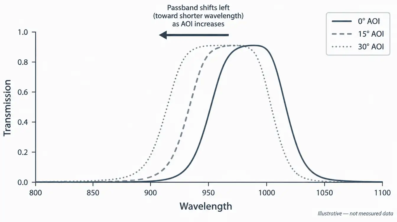
- Interference filters shift toward shorter wavelengths as AOI increases, so a datasheet curve at normal incidence may not match your system’s response.
- Hard and soft dielectric coatings trade environmental durability against deposition flexibility and achievable spectral profile.
- An accurate quote requires wavelength range, substrate, dimensions, coating and blocking requirements, AOI, inspection criteria and quantity.
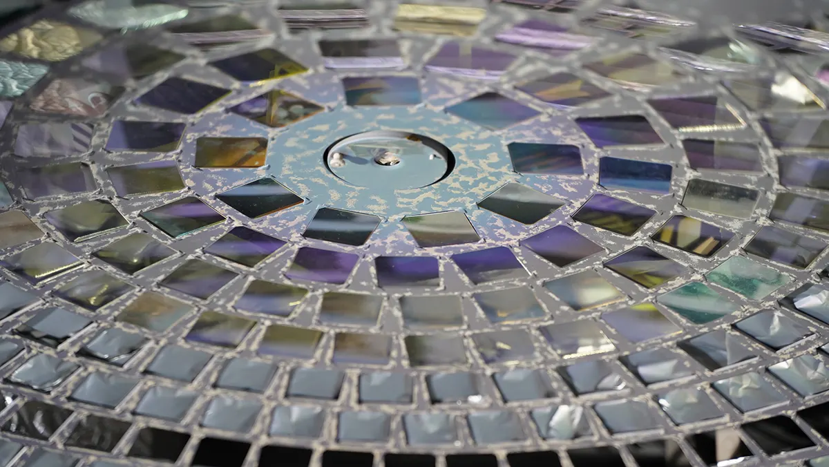
An infrared filter manufacturer designs, coats and verifies optical filters that transmit or block specific infrared wavelength bands, using substrates such as germanium, silicon, zinc selenide and sapphire. Manufacturing capability depends on coating technology, dimensional processing and the ability to verify spectral performance at the actual angle of incidence an application uses.
This distinction matters when comparing manufacturers, because two suppliers can list the same substrate and wavelength range on a datasheet while differing in coating durability, out-of-band blocking depth, and the conditions under which their spectral curves were actually measured.
What an Infrared Filter Manufacturer Actually Does
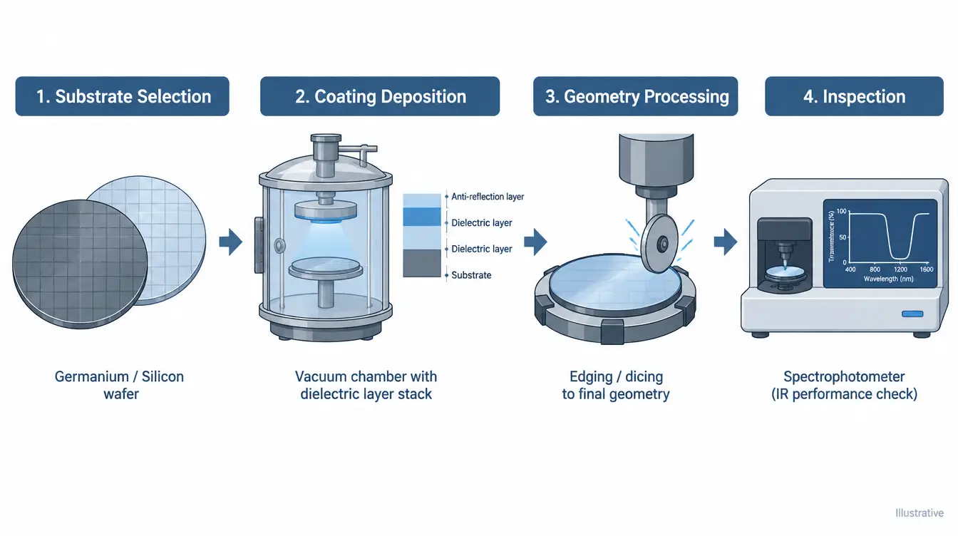
Infrared filter manufacturing covers four linked steps: selecting a substrate that transmits the required wavelength range, choosing a filter design approach, depositing and controlling the coating, and verifying the finished part against spectral and mechanical acceptance criteria. Each step constrains the others. A substrate with strong intrinsic absorption in part of the infrared limits which coating designs are practical, and a coating built from many layers changes how the finished part responds to angle of incidence and temperature.
Absorptive infrared filters rely on the substrate’s own optical properties, such as doped or colored glass that absorbs certain wavelengths while transmitting others. They are comparatively insensitive to angle of incidence, but their blocking depth and edge steepness are set by the material itself rather than by coating design. Interference filters use alternating high- and low-refractive-index dielectric layers deposited on a substrate; multiple reflected beams interfere constructively within a narrow band and destructively elsewhere, which allows sharper edges, deeper out-of-band blocking, and multi-band designs, at the cost of sensitivity to angle of incidence and to coating uniformity across the clear aperture. GIAI’s infrared filter and infrared optics product family spans both design approaches across these substrates.
Substrate Materials Used in Infrared Filter Manufacturing
Substrate choice sets the outer limits of what an infrared filter can do before any coating is applied, because a material that does not transmit in a given wavelength range cannot be used there regardless of coating design. Germanium, silicon, zinc selenide and sapphire cover different, overlapping segments of the infrared spectrum and bring different mechanical and thermal trade-offs to a manufacturing project. Background on these substrates is maintained in the infrared optical materials resource.
| Substrate | IR Range | Refractive Index | Manufacturing Trade-off |
|---|---|---|---|
| Germanium (Ge) | ~2–14 μm | ~4.0 at 10.6 μm | High reflectance without AR coating; transmission degrades at elevated temperature |
| Silicon (Si) | ~1.2–6 μm, further in high-resistivity material | ~3.4 at 5 μm | Hard and brittle; lower raw material cost than germanium |
| Zinc Selenide (ZnSe) | ~0.5–15 μm | ~2.4 at 10.6 μm | Broadest single-material range; softer, more scratch-sensitive surface |
| Sapphire (Al₂O₃) | ~0.2–5 μm | ~1.75, visible–NIR | Very hard and chemically resistant; shorter-wave cutoff limits long-wave IR use |
Material selection is rarely a single-criterion decision. A project that needs long-wave infrared transmission and can tolerate a high-index surface will usually point toward germanium; one that also needs mechanical robustness against abrasion, or a wider environmental temperature range, may trade spectral range for sapphire’s hardness or zinc selenide’s broader single-material coverage.
Material and Coating Trade-offs in Infrared Filter Manufacturing
Every infrared filter substrate and coating choice trades one property for another; no single material or deposition method maximizes transmission, durability and spectral precision at the same time. Two trade-offs matter most when comparing manufacturers: the reflection loss introduced by high-index substrates, and the durability-versus-flexibility trade-off between coating deposition methods.
Germanium’s refractive index near 10.6 μm is close to 4.0. At normal incidence, with no absorption and an air interface (n = 1), the Fresnel reflectance at a single uncoated surface is R = ((n1 − n2) / (n1 + n2))², which equals ((4.0 − 1) / (4.0 + 1))² ≈ 0.36, or roughly 36% per surface. This is a calculated value based on the stated refractive indices at normal incidence, not a measured product result, and it excludes absorption and the second surface. It is also why germanium infrared filters are almost never supplied without an antireflection coating. Silicon, with an index close to 3.4, shows a smaller but still significant single-surface reflectance near 30% under the same assumptions.
Coating deposition method introduces a separate trade-off. Densely packed, ion-assisted or ion-beam-sputtered dielectric coatings resist humidity, abrasion and thermal cycling better than the same layer structure built by conventional thermal evaporation, because higher-energy deposition processes produce lower-porosity films with fewer moisture-absorbing voids. Conventional evaporation, in turn, can offer more flexibility in layer count and material combinations for a given spectral target. Neither approach is universally better; the choice depends on the operating environment the filter has to survive and the spectral profile the application needs.
Why Angle of Incidence Changes What “Meeting Spec” Means
An infrared interference filter’s transmission peak is set by the optical path length light travels through its dielectric layer stack, and that path length shortens as the angle of incidence increases. As a result, the passband shifts toward shorter wavelengths as AOI increases from normal incidence, and the size of that shift depends on the layer design and the effective refractive index of the stack rather than on the substrate material alone.
Absorptive infrared filters are comparatively insensitive to AOI because their spectral response comes from bulk material absorption rather than thin-film interference, which is one reason engineers sometimes combine filter types within the same optical path: an interference bandpass filter for spectral selectivity, paired with an absorptive element for additional out-of-band blocking that does not shift with angle.
Because of this angle sensitivity, spectral verification for an infrared interference filter has to state the AOI, the cone half-angle if the beam is converging or diverging rather than collimated, and whether the measurement used polarized or unpolarized light, since s- and p-polarized components shift by different amounts away from normal incidence. A manufacturer’s quality verification process should tie transmission and blocking data to these conditions rather than reporting a single unqualified curve.
Common Mistakes When Sourcing an Infrared Filter
- Comparing spectral curves without matching AOI. Two filters can look identical at normal incidence and differ once tilted into the actual optical path.
- Treating “infrared filter” and “IR-cut filter” as interchangeable. An IR-cut filter blocks a broad infrared region to protect a visible-light sensor, while an infrared bandpass filter isolates a narrow band within the infrared — the design intent differs even when the coating technology overlaps.
- Assuming uniform performance across the full clear aperture. Coating thickness uniformity varies slightly across a deposition run, so a curve measured at the center of a witness sample does not automatically describe every point on a large-aperture part.
- Ignoring blocking range outside the passband. A filter with a clean passband but shallow blocking elsewhere can still leak enough out-of-band signal to affect a broadly responsive detector.
- Overlooking cone half-angle in converging beams. In a fast imaging system, rays reach the filter across a range of angles rather than a single AOI, which broadens and shifts the effective passband compared with a collimated beam.
- Assuming one durability test covers every environment. Humidity, thermal cycling and abrasion resistance are usually evaluated by separate tests, so passing one does not confirm performance against another that matters for a specific installation.
What to Send an Infrared Filter Manufacturer for an Accurate Quote
An infrared filter RFQ is complete when it specifies what the part has to do optically and how it will be tested, not just its nominal wavelength.
- Center wavelength or spectral band, and passband width (FWHM) if applicable
- Substrate material, if a specific one is required, or the target wavelength range if material selection is open
- Dimensions, clear aperture and thickness
- Coating type and blocking requirement — cut-on/cut-off wavelength and blocking range, or absorptive glass type
- Angle of incidence and beam geometry (collimated, converging or diverging) in actual use
- Polarization state, if the optical path is polarized
- Operating temperature and environment, if outside typical indoor conditions
- Inspection criteria and documentation requirements
- Quantity
GIAI reviews custom infrared filter projects against the drawing, sample, wavelength range, substrate, coating and inspection requirements listed above before defining the manufacturing route, drawing on the manufacturing capabilities and certifications and compliance information published on the English site.
FAQ
What is an infrared filter used for?
Infrared filters isolate or block specific wavelength bands within the infrared spectrum so a sensor responds only to the light relevant to its measurement. Common uses include thermal imaging, gas sensing by absorption spectroscopy, LiDAR receiver channels, fluorescence detection, and IR-cut filtering that protects visible-light image sensors from unwanted infrared signal.
What materials are infrared filters made from?
Infrared filters use substrates chosen for transmission in the target wavelength range, most commonly germanium and silicon for mid- and long-wave infrared, zinc selenide for broad mid-infrared coverage, and sapphire where shorter-wave transmission and mechanical durability both matter. The substrate is then combined with an absorptive or interference coating to define the actual passband.
What is the difference between an IR-cut filter and an infrared bandpass filter?
An IR-cut filter blocks a broad region of infrared light, typically to keep it from reaching a visible-light image sensor, while an infrared bandpass filter transmits a narrow, specific band within the infrared spectrum for sensing or imaging at that wavelength. Both can use interference coatings, but they serve opposite optical purposes.
How does angle of incidence affect an infrared filter’s performance?
For interference-coated infrared filters, increasing the angle of incidence shortens the effective optical path through the coating layers, which shifts the transmission passband toward shorter wavelengths. Absorptive infrared filters, which rely on bulk material absorption rather than thin-film interference, are much less sensitive to angle of incidence.
Can infrared filters be custom manufactured for a specific wavelength?
Yes. Infrared filter manufacturers can design custom center wavelengths, bandwidths and blocking ranges by adjusting the substrate, coating layer structure and deposition process, based on a drawing, sample or written optical specification. Feasibility still depends on the wavelength range, required blocking depth, and the angle of incidence the part will see in use.
References
- Klocek, P. (Ed.), Handbook of Infrared Optical Materials, Marcel Dekker.
- Macleod, H.A., Thin-Film Optical Filters, CRC Press / Taylor & Francis.
- ISO 9211 series, Optics and photonics — Optical coatings (Parts 1–4).
- ASTM E275, Standard Practice for Describing and Measuring Performance of Ultraviolet, Visible, and Near-Infrared Spectrophotometers.
- SPIE Field Guide to Infrared Systems, Detectors, and FPAs, SPIE Press.
Submit the specification package above to GIAI’s technical team through the contact page for a project-specific evaluation, including the wavelength range, substrate, dimensions, coating and blocking requirements, angle of incidence, inspection criteria and expected quantity.