
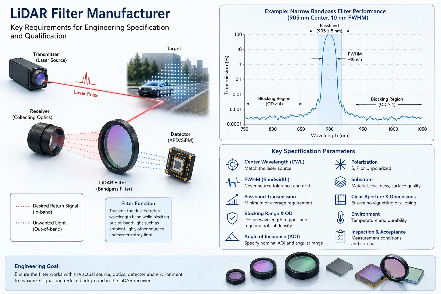
A LiDAR filter manufacturer should be evaluated on more than whether it can supply a filter centered near the laser wavelength. The filter must work with the actual source spectrum, receiver field of view, detector response, angle of incidence, environmental conditions and mechanical package. For engineering qualification, specifications such as passband transmission, FWHM, out-of-band blocking, optical density, angular shift, substrate, clear aperture and inspection method must be defined together. A correctly specified receiver filter can help reduce unwanted background reaching the detector, but it cannot by itself determine LiDAR range, accuracy or system reliability.
What Does a LiDAR Filter Manufacturer Actually Need to Control?
A LiDAR receiver usually collects much more optical energy than the wanted laser return alone. Depending on the application, sunlight, artificial lighting, other active optical sources, internal reflections and stray light may also reach the receiver.
A wavelength-selective filter is commonly placed in the receiving optical path to transmit the required return band while attenuating selected out-of-band radiation. Narrowband filtering is therefore closely connected with the receiver optics and detector rather than functioning as an isolated component.
This distinction matters when qualifying a manufacturer. A spectral curve measured at one nominal condition does not automatically establish performance inside the final LiDAR assembly.
The engineering requirement may involve:
- Target transmission wavelength
- Source linewidth and wavelength tolerance
- Full width at half maximum
- Minimum or average passband transmission
- Blocking wavelength range
- Required optical density
- Nominal angle of incidence
- Angular range or cone angle
- Polarization condition
- Substrate material
- Clear aperture
- External dimensions and thickness
- Surface quality
- Flatness or transmitted-wavefront requirements
- Temperature and environmental conditions
- Inspection and production acceptance criteria
These parameters should be treated as an integrated specification rather than independent numbers.
Do Not Specify a LiDAR Filter by Wavelength Alone
There is no single wavelength used by every LiDAR system. Different laser-ranging and remote-sensing architectures operate at different wavelengths according to the source, detector, application and system design. Operational lidar instruments have, for example, used 532 nm and 1064 nm channels, while near-infrared LiDAR products and optical filters are also designed around other bands.
GIAI Photonics currently lists both BP905 and BP1550 filter examples associated with laser-ranging or LiDAR applications. These examples demonstrate why “LiDAR filter” is a functional category rather than one universal spectral specification.
The nominal laser wavelength is therefore only the starting point.
An engineering team should also determine whether the source wavelength changes because of:
- Device tolerance
- Operating temperature
- Source linewidth
- Production variation
- Drive condition
- System architecture
If the passband is specified too narrowly around a room-temperature nominal wavelength, part of the intended return may fall outside the effective filter transmission band under other operating conditions.
Center Wavelength and FWHM Must Be Evaluated Together
For a bandpass filter, center wavelength describes the approximate central position of the transmission band, while full width at half maximum describes the spectral width between the half-maximum transmission points.
Neither parameter is sufficient by itself.
Consider a simplified hypothetical specification:
| Parameter | Illustrative Requirement |
|---|---|
| Nominal source wavelength | 905 nm |
| Filter center wavelength | Defined around system requirement |
| FWHM | Defined after source and angular analysis |
| Passband transmission | Minimum or average requirement stated |
| Blocking | Defined wavelength regions |
| AOI | Nominal angle plus permitted range |
These values are illustrative only and are not GIAI Photonics measured specifications.
A narrower FWHM can reduce some unwanted background, but making the passband increasingly narrow is not automatically beneficial. The filter still needs to accommodate source variation, coating tolerance, temperature behavior and angular spectral shift.
The engineering goal is adequate transmission of the useful return while controlling background reaching the detector.
Why Angle of Incidence Is Critical in LiDAR Filters
Angle of incidence is one of the most important parameters to discuss with a LiDAR filter manufacturer.
Thin-film interference filters are angle dependent. As the incident angle changes, the spectral position of the passband can change; conventional interference-bandpass behavior commonly shifts toward shorter wavelengths as incidence angle increases. Experimental filter designs demonstrate substantial center-wavelength tuning with changing incidence angle.
This becomes important in LiDAR receivers because the filter may not see a single collimated ray at 0°.
A practical receiver can contain:
- A finite field of view
- Converging or diverging beams
- Off-axis field rays
- Scanning optics
- Lens-generated cone angles
Different rays may therefore strike the filter at different incidence angles.
A spectral curve specified only at normal incidence may not represent the effective transmission seen by the complete receiver.
When requesting a filter, engineers should communicate the nominal AOI together with the expected angular distribution. For wider-angle systems, filter position within the optical path may also affect the effective spectral requirement.
Polarization Can Matter at Oblique Incidence
At normal or near-normal incidence, polarization effects may be relatively limited for many conventional filter designs. At larger incidence angles, however, S- and P-polarized light can experience different spectral responses.
This is particularly important when the LiDAR architecture, scanning element or optical path creates significant angular incidence.
The specification should therefore state whether testing is required for:
- Unpolarized light
- S polarization
- P polarization
- A defined system polarization state
For applications with significant AOI, the manufacturer should not assume that a normal-incidence unpolarized spectrum represents the installed condition. Optical-filter research specifically addresses polarization-dependent behavior and filter design at oblique incidence.
Blocking Range Is More Important Than an OD Number Alone
Optical density describes attenuation:
OD = −log10(T)
where T is fractional transmittance.
For example, an OD4 region corresponds to a transmittance of 0.0001, or 0.01%.
But specifying “OD4” without defining the wavelength range is incomplete.
A LiDAR receiver is affected by optical radiation over the spectral region where the detector and other system components respond. The required blocking therefore needs defined wavelength boundaries.
A meaningful specification might divide the rejection requirement into several wavelength regions rather than assigning one universal OD value.
Engineers should confirm:
- Blocking wavelength range
- Required OD in each region
- Whether OD is minimum or average
- Measurement AOI
- Polarization condition
- Measurement-system capability
Deep blocking also places demands on measurement dynamic range and stray-light control. A manufacturer should be able to define how the requested blocking performance will be verified rather than supplying only a visually attractive spectral curve.
Peak Transmission Is Not the Same as Passband Performance
A high peak transmission value describes only the highest point of the passband.
It does not tell an engineer:
- Transmission across the full useful band
- Passband shape
- Edge behavior
- Transmission at temperature extremes
- Transmission at angular extremes
- Lot-to-lot spectral variation
Depending on the application, an acceptance specification may therefore use minimum transmission across a defined wavelength interval or average transmission within the passband rather than peak transmission alone.
The definition should be written explicitly so that both engineering and inspection teams evaluate the same criterion.
Match the Filter to the Detector Response
The detector determines which wavelengths can become electrical signals.
Out-of-band optical energy outside the detector’s meaningful response may require less attention than radiation within a high-responsivity region, while strong environmental sources inside that response range may require deeper rejection.
For this reason, the source spectrum, infrared filters, receiver optics and detector response should be considered together.
A LiDAR filter manufacturer may need information such as:
- Detector type or response curve
- Source spectrum
- Expected ambient spectrum
- Receiver aperture
- Field of view
- Lens f-number or cone angle
- Filter position
This allows the blocking range and passband to be based on the actual optical system rather than a generic catalog curve.
Substrate Selection Is Part of the Optical Design
The coating is only one part of a finished LiDAR filter.
The substrate also influences:
- Spectral compatibility
- Mechanical strength
- Thickness
- Surface quality
- Flatness
- Thermal response
- Packaging
- Available clear aperture
The transmission range of a substrate should not be treated as the transmission performance of the finished coated component. The final spectrum depends on the substrate, coatings and actual measurement conditions.
If the filter doubles as a protective window in front of the receiver, mechanical and environmental requirements become even more important.
The engineering drawing should define dimensions and tolerances independently from the spectral specification.
Clear Aperture and Mechanical Size Are Different
External dimensions describe the physical part.
Clear aperture describes the region where the optical specification must be maintained for the working beam.
These values are not necessarily identical.
Edge exclusion, coating fixtures, bevels, mounting surfaces, adhesive areas and retaining structures may reduce the usable optical area. A filter that physically fits the housing can still clip or degrade the working beam if the clear aperture is inadequate.
For this reason, drawings should define both overall dimensions and required optical aperture.
Surface Quality, Flatness and Wavefront Requirements Should Match the Optical Function
Not every LiDAR receiver requires imaging-grade optical specifications, and unnecessarily tight surface requirements can increase manufacturing difficulty without improving system performance.
Surface quality may matter when scratches, digs, contamination or coating defects could introduce scatter.
Flatness or transmitted wavefront may become more important when the filter is located in an imaging or collimated optical path where deformation of the transmitted wavefront affects system behavior.
The requirement should be driven by the optical architecture.
A non-imaging energy-collection receiver and a high-resolution imaging LiDAR system may therefore use very different mechanical and surface specifications even when their spectral bands are similar.
A Manufacturer Should Be Qualified by Measurement Conditions
A spectral report is useful only when the measurement conditions are understood.
For engineering qualification, determine whether the measurement identifies:
- Wavelength range
- Angle of incidence
- Polarization
- Measurement position
- Spectral resolution where relevant
- Peak, minimum or average criteria
- Blocking measurement capability
A spectrum measured at 0° should not automatically be assumed to represent performance at a substantially different operating angle.
Likewise, a measurement at the center of a sample may not be enough when coating uniformity across a large clear aperture is important.
The inspection plan should reflect the risks of the specific optical design.
Prototype Qualification Should Precede Production Acceptance
Passing a standalone filter measurement does not establish complete LiDAR performance.
After optical inspection, representative samples should be evaluated in the assembled receiver under relevant operating conditions.
Potential validation variables include:
- Ambient illumination
- Target reflectance
- Range
- Temperature
- Field angle
- Optical alignment
- Transmitter-to-receiver crosstalk
- Window reflections
- Contamination
- Mechanical assembly tolerance
A filter can help suppress part of the unwanted background reaching a detector, but system performance also depends on the laser source, receiver aperture, detector, optics, electronics, processing algorithms, target and environment.
Prototype approval and production acceptance should therefore be treated as two related but distinct stages.
Engineering Checklist for Evaluating a LiDAR Filter Manufacturer
| Requirement | What the Engineer Should Define | Why It Matters |
| Operating wavelength | Source spectrum, tolerance and drift | Establishes required passband |
| CWL | Target spectral position and tolerance | Controls spectral alignment |
| FWHM | Required transmission bandwidth | Balances signal and background |
| Transmission | Peak, average or minimum | Prevents ambiguous acceptance |
| Blocking | Wavelength ranges and OD | Defines unwanted-light suppression |
| AOI | Nominal angle and angular range | Accounts for spectral shift |
| Polarization | S, P, unpolarized or defined state | Important at oblique incidence |
| Substrate | Material and thickness | Affects optical and mechanical behavior |
| Clear aperture | Required working area | Prevents clipping and edge-related issues |
| Surface requirements | Quality, flatness, wavefront as needed | Matches optical function |
| Environment | Temperature and exposure conditions | Defines validation conditions |
| Inspection | Spectral and dimensional criteria | Enables objective acceptance |
| Prototype stage | Sample quantity and test conditions | Supports system validation |
| Production stage | Lot and inspection requirements | Supports consistent acceptance |
Common Manufacturer-Qualification Mistakes
Selecting a filter from the laser wavelength alone
A nominal wavelength does not describe source drift, linewidth, filter AOI or detector response.
Asking for the narrowest possible bandwidth
Narrower is not automatically better. If the required laser-return band moves outside the effective passband, useful signal can be lost.
Specifying OD without a wavelength range
An OD value has little engineering meaning unless the blocked spectral region is defined.
Evaluating only the normal-incidence curve
A filter used in a finite-cone or wide-field receiver can experience a different effective spectrum.
Comparing suppliers only by peak transmission
Peak transmission does not describe the full passband, blocking, angular response, substrate, dimensions or inspection conditions.
Treating the filter as the source of LiDAR accuracy
A receiver filter performs spectral selection. It does not increase emitted laser power and cannot independently guarantee detection distance, ranging accuracy or overall system reliability.
What Information Should Be Sent to the Manufacturer?
For a new LiDAR filter project, a useful technical package can include:
- LiDAR architecture and application
- Source wavelength and spectral data
- Source tolerance and temperature behavior
- Detector response curve
- Required passband or desired CWL
- FWHM requirement
- Minimum or average transmission requirement
- Blocking ranges and required OD
- Nominal AOI
- Field of view or cone-angle information
- Polarization condition
- External dimensions and thickness
- Clear aperture
- Substrate preference, if already defined
- Surface quality and flatness requirements
- Temperature and environmental conditions
- Mechanical drawing or assembly information
- Inspection requirements
- Prototype quantity
- Expected production requirements
When the optical design is not finalized, the source spectrum, detector response, receiver geometry and mechanical constraints are often more useful than requesting a filter using only a nominal wavelength.
GIAI Photonics provides optical filters, including bandpass filters, narrow bandpass filters and infrared filters. Its current product catalog also includes examples associated with 905 nm and 1550 nm laser-ranging applications. Final component specifications should still be established from the actual optical system, drawing and agreed inspection criteria rather than generalized catalog descriptions.
Final Engineering Considerations
Selecting a LiDAR filter manufacturer is ultimately a specification and qualification problem rather than a search for the highest transmission or deepest OD number.
The filter must transmit the useful return under real wavelength and angular conditions, reject relevant background over defined spectral regions, fit the mechanical assembly and remain objectively measurable against agreed acceptance criteria.
The most useful specification therefore connects five elements:
source → receiver optics → filter → detector → operating environment
When wavelength, bandwidth, blocking, AOI, polarization, substrate, dimensions and inspection conditions are defined together, engineers can compare prototype results and production components on a technically meaningful basis.
For projects involving nonstandard wavelengths, narrow passbands, defined angular ranges, special substrates or mechanical integration, engineers may provide wavelength requirements, drawings, samples, operating conditions and inspection requirements to GIAI Photonics for component evaluation.
FAQ
What type of optical filter is normally used in a LiDAR receiver?
A bandpass or narrow bandpass filter is commonly considered when the receiver needs to transmit a defined laser-return wavelength while attenuating selected out-of-band radiation. The appropriate design depends on source spectrum, detector response, ambient conditions, AOI and receiver geometry. A narrowband filter should not be selected from nominal wavelength alone.
Is 905 nm the standard wavelength for every LiDAR system?
No. LiDAR systems can operate at different wavelengths depending on the application, source and detector architecture. 905 nm is used in some near-infrared ranging systems, while other LiDAR implementations use wavelengths such as 1550 nm, 1064 nm or 532 nm. The filter specification must follow the actual system rather than an assumed universal LiDAR wavelength.
How narrow should a LiDAR filter be?
There is no universal optimum FWHM. The passband needs to cover the useful source spectrum after accounting for source tolerance, thermal drift, coating tolerance, AOI and beam geometry. Making a filter narrower may reduce some background but can also attenuate the desired return if the effective passband no longer overlaps the source.
Why must AOI be provided to a LiDAR filter manufacturer?
Because interference-filter spectra change with incidence angle. A filter measured at normal incidence can have a different spectral position when installed in an angled or converging optical path. Engineers should therefore define nominal AOI as well as the expected angular range or cone angle.
What OD should a LiDAR filter have?
OD should be defined together with a wavelength range. There is no universal blocking value suitable for every LiDAR receiver. The appropriate requirement depends on detector response, environmental spectrum, allowed background level and complete receiver design. Inspection capability must also be sufficient to verify the requested blocking level.
What should be tested before approving a LiDAR filter for production?
First confirm the agreed spectral, dimensional and surface requirements. Then validate representative samples in the assembled optical system under relevant temperature, ambient-light, field-angle, target and alignment conditions. A standalone spectral measurement establishes filter performance under its stated test conditions, not complete LiDAR system performance.