
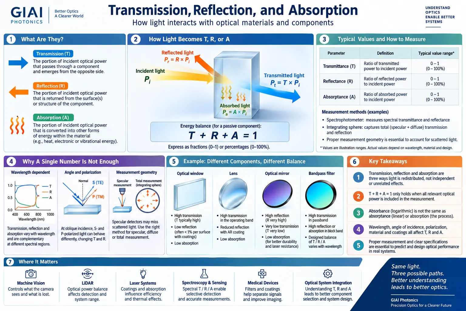
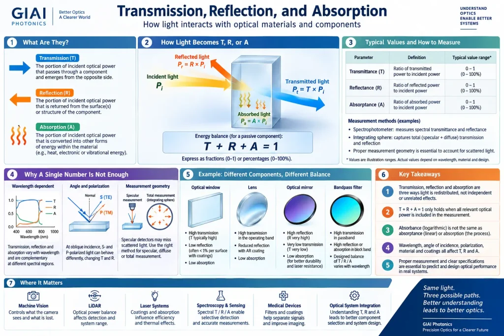
Transmission, reflection, and absorption describe three fundamental ways light interacts with an optical material or component. Transmission is the portion of incident optical power that passes through the component, reflection is the portion returned from its surfaces or optical structure, and absorption is the portion converted into other forms of energy within the material. Understanding how optical power is divided among these three paths is important when evaluating filters, lenses, windows, mirrors, coatings, detectors, and complete optical systems.
The Three Possible Paths for Incident Light
Suppose optical power Pi reaches an optical component. Some of that power may emerge through the opposite side, some may return toward the incident side, and some may be absorbed within the material or coating.
The corresponding dimensionless quantities are:
- T = transmittance
- R = reflectance
- A = absorptance
- Pi = incident optical power
- Pt = transmitted optical power
- Pr = reflected optical power
- Pa = absorbed optical power
Transmittance, reflectance, and absorptance can be expressed as fractions between 0 and 1 or as percentages.
This power balance applies to a passive optical component when the relevant transmitted, reflected, and absorbed optical power is accounted for within the same measurement boundary.
What Is Transmission?
Transmission occurs when light enters an optical component and emerges from the other side. Transmittance describes how much of the incident optical power completes this process.
For example, if a component has 90% transmittance under specified conditions, 90% of the measured incident optical power emerges through the defined transmission path. The percentage alone, however, is not a complete optical specification.
Optical transmission can depend on:
- Wavelength
- Substrate material
- Material thickness
- Coating design
- Angle of incidence
- Polarization
- Surface condition
- Scattering
- Temperature and environment
- Measurement aperture and geometry
For this reason, engineers commonly evaluate spectral transmittance, meaning transmission as a function of wavelength, rather than treating transmission as one fixed number.
An optical window, for example, may use a material that has good intrinsic transparency in the required wavelength range. The transmission of the finished window can still be lower because of surface reflection, bulk absorption, coating characteristics, contamination, scattering, and other losses.
What Is Reflection?
Reflection occurs when part of the incident light returns from an interface or optical structure instead of continuing through it. Reflectance describes the ratio of reflected optical power to incident optical power.
Reflection can occur even when an optical material appears highly transparent. One important reason is the change in refractive index that occurs when light crosses an interface between two different optical media.
For two non-absorbing dielectric media at normal incidence, a simplified Fresnel reflectance expression is:
Here, n1 and n2 represent the refractive indices on the two sides of the interface.
As a simplified example, consider light traveling from air, with a refractive index close to 1.0, into a dielectric optical material with a refractive index close to 1.5. The calculated normal-incidence reflection from one uncoated interface is approximately 4%.
An optical component with two surfaces therefore cannot be evaluated by considering material absorption alone.
Anti-reflection coatings can reduce surface reflection over a defined wavelength range and range of incidence conditions. When absorption and other losses remain low, reducing reflection generally allows more incident optical power to reach the transmitted beam.
However, low reflection should not automatically be interpreted as a complete transmission specification because absorption, scattering, additional surfaces, and other optical losses may still be present.
What Is Absorption?
Absorption occurs when optical energy is taken up by a material rather than leaving the component as transmitted or reflected light.
Depending on the optical material and wavelength, absorbed energy may eventually appear as heat or participate in electronic, vibrational, chemical, or other material processes.
Absorption is strongly wavelength dependent. A material that transmits visible wavelengths efficiently may absorb ultraviolet or infrared radiation strongly. Likewise, an infrared optical material may perform well in one infrared region while being unsuitable at other wavelengths.
Material thickness also matters. Under simplified conditions in which reflection and scattering are treated separately, internal transmission through an absorbing material can be represented using an exponential attenuation relationship:
α represents the absorption coefficient and L represents the optical path length through the material.
The practical consequence is that describing a substrate simply as “transparent” is rarely sufficient for an engineering specification. Its transmission and absorption behavior should be considered for the required wavelength band, thickness, grade, and operating conditions.
Absorption, Absorptance, and Absorbance Are Different
These three terms are related, but they should not be used interchangeably.
| Term | Meaning | Typical Use |
|---|---|---|
| Absorption | The physical process by which optical energy is taken up by a material. | Describing light-material interaction. |
| Absorptance | The fraction of incident radiant power absorbed by a component. | Optical power balance and material characterization. |
| Absorbance | A logarithmic quantity related to transmittance. | Spectroscopy and quantitative optical measurements. |
Absorbance is commonly expressed as:
This means an absorptance of 0.5 is not the same thing as an absorbance of 0.5. The distinction is particularly important when interpreting spectroscopy data, neutral-density attenuation, optical density specifications, and material measurements.
Why T + R + A Requires Measurement Context
The expression T + R + A = 1 provides a useful description of optical power conservation, but applying it to real measurements requires a clearly defined measurement geometry.
Consider a surface that scatters light. A detector positioned directly behind the sample may collect only a narrow forward-transmitted beam. Light scattered to larger forward angles may not reach that detector.
Similarly, a reflection measurement may detect only specular reflection while missing diffuse reflected light.
If these uncollected components are treated as missing optical power, calculating absorptance simply as:
can produce a misleading result.
Why Wavelength Changes Transmission, Reflection, and Absorption
In practical optics, transmission, reflection, and absorption are usually spectral quantities:
The same optical component may therefore have high transmission at one wavelength and high reflection or absorption at another.
This wavelength dependence is fundamental to optical filters.
An interference filter can use multilayer thin-film interference to create a high-transmission passband while rejecting unwanted wavelengths largely through reflection. An absorptive filter relies more strongly on wavelength-dependent absorption within the optical material.
Real filters may combine several mechanisms. For this reason, blocked light should not automatically be assumed to be absorbed.
The distinction has practical system consequences. Reflected energy returns into the optical system and may interact with other surfaces, while absorbed energy may contribute to heating of the optical component.
Angle of Incidence and Polarization Also Matter
Spectral performance measured at normal incidence should not automatically be assumed to remain unchanged when an optical component is used at a substantial angle.
For multilayer thin-film coatings, changing the angle of incidence can shift spectral features. At oblique incidence, S-polarized and P-polarized light can also exhibit different transmission and reflection behavior.
This is especially relevant to components such as:
- Interference filters
- Dichroic filters
- Beam splitters
- Coated optical windows
- Laser optics
- Scanning optical systems
In a converging or diverging beam, rays may reach the coating across a range of incidence angles rather than at one single AOI.
Where angle sensitivity is significant, an optical specification should therefore define the wavelength range, nominal angle of incidence, angular range or cone angle, and polarization state when applicable.
How Optical Coatings Redistribute Optical Power
An optical coating does not simply “increase transmission” or “increase reflection” in isolation. The coating changes how incident optical power is distributed among transmission, reflection, and absorption.
Anti-Reflection Coatings
An anti-reflection coating is designed to reduce reflected optical power over a specified wavelength and angular range. If substrate and coating absorption are sufficiently low, more optical power can then remain in the transmitted beam.
High-Reflection Coatings
A reflective coating is designed to direct a high proportion of the incident optical power into the reflected beam over its intended wavelength range.
Optical Filter Coatings
Thin-film filters can deliberately produce high transmission in selected spectral regions and strong rejection elsewhere. Depending on coating construction and substrate properties, rejected energy may be reflected, absorbed, or divided between both mechanisms.
For engineering evaluation, a transmission spectrum therefore does not always reveal what happens to all of the rejected optical energy.
How the Balance Changes for Different Optical Components
| Optical Component | Typical Intended Behavior | Important Considerations |
|---|---|---|
| Optical Window | High transmission in the operating wavelength range. | Material absorption, surface reflection, coating, thickness, wavefront effects and environment. |
| Lens | High transmission while refracting light to control imaging or beam propagation. | Material transmission, Fresnel reflection, AR coating, surface quality and multiple optical surfaces. |
| Optical Mirror | High reflection in the intended spectral range. | Coating design, wavelength, AOI, polarization, substrate and absorption. |
| Bandpass Filter | High transmission in a selected passband and strong rejection outside it. | Center wavelength, bandwidth, blocking, AOI, polarization and rejection mechanism. |
| Dichroic Component | Transmit one wavelength region while reflecting another. | Wavelength, angle, polarization and coating design. |
For optical mirrors, reflection is intentionally dominant within the design wavelength range. For windows and many lenses, transmission is normally the desired path. Optical filters deliberately change the balance according to wavelength.
The most useful engineering question is therefore not simply whether an optical material is transparent or reflective. A better question is:
How Are Transmission and Reflection Measured?
Spectrophotometric measurements can characterize wavelength-dependent transmission and reflection by comparing optical power under defined reference and sample conditions.
A transmission measurement evaluates optical power emerging through the sample relative to the incident reference. A reflection measurement evaluates optical power returned from the sample.
For a strongly specular optical component, the detector geometry may be arranged specifically for the reflected or transmitted beam. When significant scattering is present, an integrating sphere or another appropriate collection geometry may be used when total transmitted or reflected optical power is required.
A useful optical measurement report should identify relevant conditions such as:
- Wavelength range
- Spectral resolution
- Angle of incidence
- Polarization
- Sample orientation
- Measurement aperture
- Measurement geometry
- Specular, diffuse, regular, or total measurement
- Whether the result applies to the substrate, coating, or finished component
Without these conditions, two measurements showing different numerical values may not necessarily indicate that either measurement is incorrect. They may have been obtained under different optical conditions.
Common Misunderstandings
Why These Three Quantities Matter in Optical Systems
The transmission-reflection-absorption balance influences many optical applications.
Machine Vision and Imaging
Transmission determines how much useful optical signal reaches the imaging path, while reflection and scattering can contribute to unwanted light or reduced contrast. Final imaging performance still depends on the complete optical and electronic system.
Spectroscopy and Optical Sensing
Spectral transmission and absorption can be used to separate or quantify wavelength-dependent signals. Measurement geometry, detector response, source spectrum, calibration, and optical path length all affect the final result.
Laser Systems
Reflection, transmission, and absorption are particularly important because absorbed optical energy can contribute to component heating. High reflectance alone should not be interpreted as proof of high laser damage resistance.
Medical and Analytical Instruments
Filters, coatings, lenses, and windows can contribute to wavelength selection and background suppression. The final signal reaching a detector depends on the complete system, including the source, detector, optics, electronics, calibration, and operating environment.
Frequently Asked Questions
Does transmission + reflection + absorption always equal 100%?
For a passive optical component, conservation of energy gives T + R + A = 1 when all relevant transmitted, reflected, and absorbed optical power is accounted for within the same measurement boundary. In experimental measurements, however, scattered light may fall outside the detector aperture. If only regular transmission and specular reflection are measured, the missing portion should not automatically be classified as absorption.
Is absorbance the same as absorption or absorptance?
No. Absorption is the physical process by which optical energy is taken up by a material. Absorptance is the fraction of incident optical power that is absorbed. Absorbance is a logarithmic quantity related to transmittance and is commonly used in spectroscopy.
Does lower reflection always produce higher transmission?
Reducing reflection can increase transmission when other optical losses remain small, but the relationship is not automatically one-to-one. Substrate absorption, coating absorption, scattering, contamination, and additional optical surfaces may also affect the transmitted power.
Why do transmission and reflection change with wavelength?
Optical constants, material absorption, dispersion, and thin-film interference vary with wavelength. A component can therefore transmit one spectral region while reflecting or absorbing another. This wavelength dependence is deliberately used in filters, mirrors, dichroic optics, and anti-reflection coatings.
Why does angle of incidence matter for coated optics?
Changing the angle of incidence changes the optical path through thin-film coating layers and can alter the interference condition. Spectral features may shift, and S- and P-polarized light may behave differently at oblique incidence. Performance measured at normal incidence should therefore not automatically be assumed to remain unchanged at another AOI.
Key Engineering Takeaway
Transmission, reflection, and absorption describe how incident optical power is redistributed when light interacts with an optical material or component. The relationship T + R + A = 1 provides a useful starting point, but meaningful optical analysis also requires wavelength, angle of incidence, polarization, substrate, coating, thickness, scattering, and measurement geometry to be defined. A mirror intentionally favors reflection, a window normally favors transmission, and an optical filter changes the balance according to wavelength. Understanding where the optical power goes is more useful than evaluating any one percentage in isolation.