
- A LiDAR filter’s passband width is set by the receiver’s angle range and temperature range, not by how narrow the coating can be made.
- Interference filters blue-shift with increasing angle of incidence; a higher effective coating index reduces the shift.
- Blocking range must match the detector’s spectral response, not the visible band alone.
- Narrowing the passband improves background-limited SNR only until the laser line falls outside it.
- Evaluate suppliers on coating design ownership, uniformity control, measurement at the specified AOI, and lot documentation.
A LiDAR optical filter manufacturer designs and coats the narrowband interference filters that sit in front of the receiver, passing the laser return while rejecting solar background. Choosing one is a specification exercise, not a catalog search: the supplier must hold center wavelength, angular shift, thermal drift and blocking depth across your real operating conditions.
That last point is where most sourcing decisions go wrong. A filter datasheet describes behaviour at normal incidence and room temperature. A LiDAR receiver rarely operates there. The useful question to ask a supplier is not “how narrow can you go” but “can you hold this passband over my angle range, my temperature range and my production lots”. This page sets out the specifications that decide the answer, and what to check before placing a development order.
What the filter actually does in a LiDAR receiver
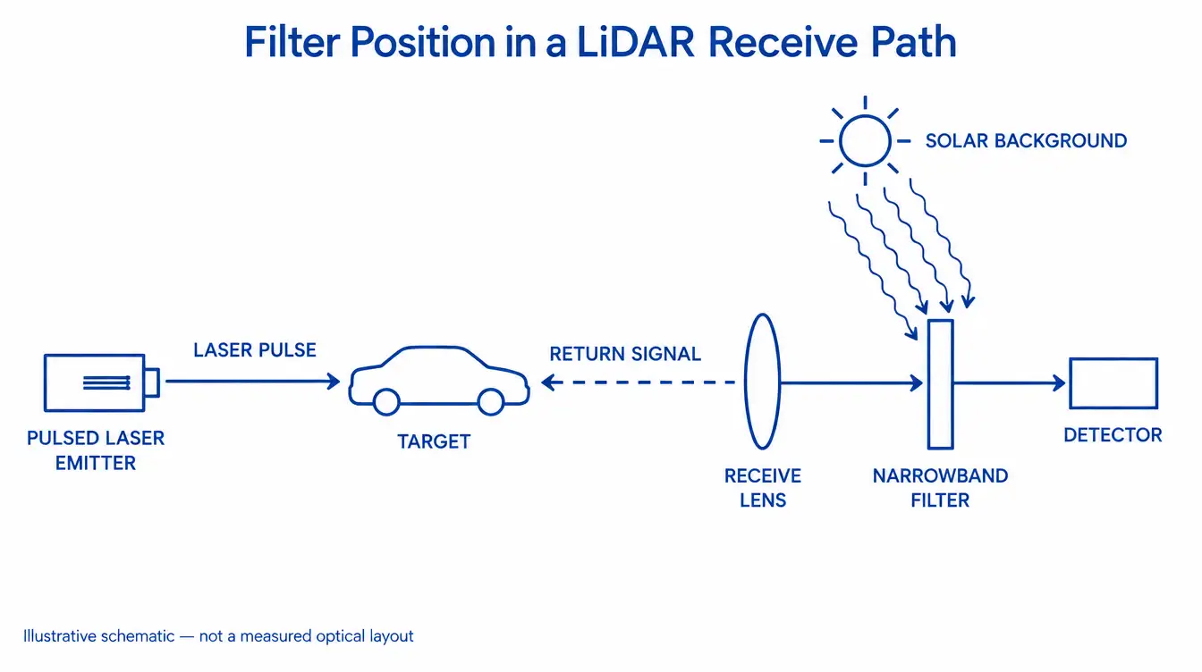
The receive-path filter isolates the laser return from everything else reaching the detector. Sunlight, headlights and other illuminators produce a broadband background; the laser produces a narrow line. A bandpass filter centred on that line passes the signal and attenuates the rest, which raises the signal-to-noise ratio at the detector.
Many systems also place a filter in the transmit path to clean up the source spectrum, though the receive path usually drives the tighter specification because it faces the full sky background. The physical mechanism is thin-film interference: a multilayer dielectric stack forms one or more resonant cavities, and the passband position follows the optical thickness of those cavities. Every effect discussed below is a change in that optical thickness, either through geometry or through material.
Which laser wavelength you build around, and what follows from it
The filter is built around the laser line, so the source wavelength is the first input to any quotation. It also determines the substrate, the detector, and how much solar background the filter has to fight.
Ground-level solar spectral irradiance falls toward longer wavelengths across the near infrared, and water vapour absorption depresses it further in specific bands, one of which sits near 940 nm. That is a background-level argument, not a reason to prefer one wavelength: source availability, eye-safety classification, detector cost and atmospheric conditions all pull in different directions.
| Wavelength | Typical detector | Solar background | Substrate notes | Blocking driver |
|---|---|---|---|---|
| 905 nm | Silicon APD / SPAD | High | Optical glass, fused silica | Silicon responds to roughly 1100 nm |
| 940 nm | Silicon APD / SPAD | Reduced by water band | Optical glass, fused silica | Same silicon response edge |
| 1064 nm | Silicon or InGaAs | Moderate | Fused silica common for pulsed use | Detector-dependent |
| 1550 nm | InGaAs | Lower | Fused silica; silicon transmits here | InGaAs response extends past 1600 nm |
Two entries in that table are worth reading twice. Silicon is opaque at 905 nm and transparent beyond about 1.1 µm, so it is available as a substrate at 1550 nm and not at 905 nm. And a blocking specification written “block the visible” is incomplete for a silicon receiver, because silicon keeps responding for roughly 200 nm above a 905 nm passband. Blocking must be specified over the range where the detector still converts photons, with the required optical density stated for that range.
Why angle of incidence sets the passband width
An interference filter passes a shorter wavelength when tilted. Increasing the angle of incidence shortens the optical path that satisfies the resonance condition inside the cavity, so the center wavelength moves toward the blue. This is the single effect that most often turns a correct-looking purchase into a receiver that loses returns at the edge of its field.
For a Fabry–Perot type interference filter in air, the standard approximation is:
λθ = λ0 × √(1 − sin²θ / neff²)
where λ0 is the center wavelength at normal incidence, θ is the angle of incidence in air, and neff is the effective index of the cavity determined by the coating design. neff is not the substrate index and not any single layer index; it comes from the stack, which is why two filters with the same nominal center wavelength can shift by different amounts. The expression assumes collimated, polarization-averaged light. At larger angles the s and p components separate and the passband broadens and loses peak transmission, so the single-number shift below understates what a real wide-angle receiver sees.
| AOI in air | CWL, neff 1.45 | CWL, neff 2.0 |
|---|---|---|
| 0° | 905.0 nm | 905.0 nm |
| 5° | 903.4 nm | 904.1 nm |
| 10° | 898.5 nm | 901.6 nm |
| 15° | 890.5 nm | 897.4 nm |
| 20° | 879.5 nm | 891.7 nm |
| 30° | 849.5 nm | 876.3 nm |
These are calculated values from the expression above with λ0 = 905 nm, not measured product data. They illustrate two things. The shift is strongly non-linear, so a receiver that accepts 20° does not need twice the margin of one that accepts 10°, it needs about four times. And a higher effective index cuts the shift substantially, which is why the coating design, and not only the passband number, belongs in the technical discussion with a supplier.
Cone angle and temperature widen the budget further
Angle of incidence is rarely a single value. A filter mounted in converging space sees a cone of angles at every field point, and different field points arrive at different mean angles. The passband seen by the system is then a blurred superposition: the band edges soften, peak transmission drops, and the effective passband differs across the field. Mounting the filter in collimated space narrows the angular spread and makes the specification tractable, at the cost of optical volume and an extra lens group.
Temperature adds a second shift, in the opposite direction. Dielectric stacks built from oxide materials with positive thermo-optic coefficients increase their optical thickness as temperature rises, so the center wavelength moves toward longer wavelengths with heating. The coefficient depends on the materials and the design, and it has to come from the supplier’s data rather than from a generic figure. Soft-coated and hard-coated filters differ here, and a filter qualified indoors can drift out of band in a sealed housing exposed to sun load.
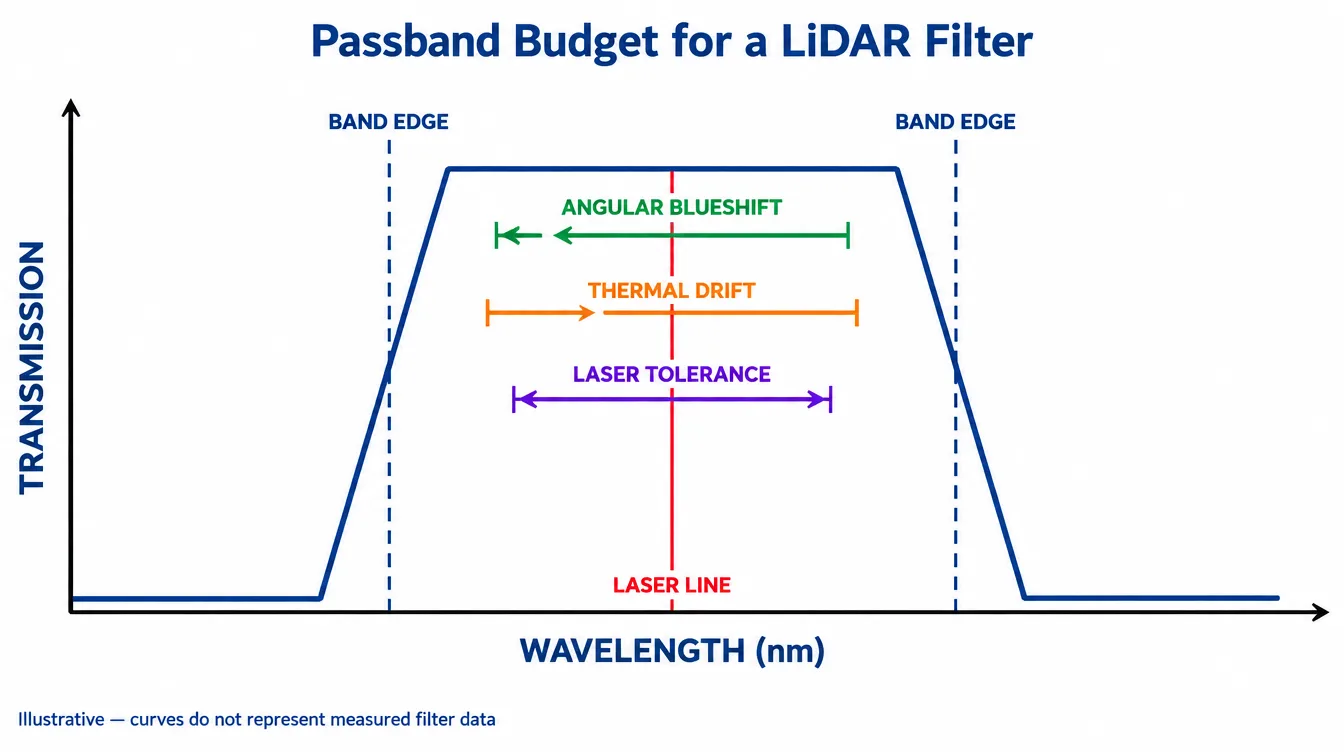
The laser itself contributes a third term. Source center wavelength has a manufacturing tolerance and its own temperature coefficient. The passband has to contain the laser line after all three contributions are added, evaluated at the worst-case corner rather than at nominal.
The trade-off: how narrow is too narrow
Narrowing the passband reduces background. For a spectrally flat background, the photon rate reaching the detector through the filter scales with passband width Δλ. When that background dominates the noise, shot noise scales with √Δλ and signal-to-noise ratio improves as 1/√Δλ. Halving the passband buys roughly a factor of 1.4 in SNR under those conditions.
Two limits stop that from being a free improvement. If detector dark current, readout noise or afterpulsing dominates rather than the solar background, narrowing gains less than the square-root law suggests, and eventually gains nothing. More importantly, once the passband is narrower than the combined angular, thermal and source-tolerance budget, the laser line falls off the band edge at some corner of the operating envelope. The loss there is not gradual noise degradation, it is missing returns at particular field angles or particular temperatures, which is far harder to diagnose in the field than a uniformly noisy image.
A practical order of work: fix the angle range and temperature range first, calculate the total wavelength excursion, add the laser tolerance, and let that sum define the minimum FWHM. Then ask whether the resulting background level meets the range requirement. If it does not, the answer is usually a higher effective-index design, a collimated mounting position or a narrower acceptance cone, not simply a narrower filter.
What separates a supplier who can build these filters
Most of the meaningful differences between filter suppliers are process control questions, and they can be asked directly during technical qualification.
Who owns the coating design
Ask whether the supplier designs the stack or purchases coated blanks. It matters because the effective index, the cavity count and the blocking architecture are design decisions, and a supplier who cannot change them can only offer you what already exists.
Uniformity across the part and across the batch
Coating thickness varies across a deposition fixture, and center wavelength follows thickness. Ask how center wavelength is mapped across a single substrate and across positions in the chamber, and what tolerance is held part to part within a lot and between lots. For a narrow passband, lot-to-lot center wavelength repeatability can matter more than the nominal specification.
Measurement at the conditions you specified
A spectrophotometer scan at normal incidence does not verify a filter intended for 15° with a 10° cone. Ask whether the supplier can measure at the specified angle, and how deep blocking is verified, since a high-transmission passband and deep out-of-band rejection cannot normally be captured in the same instrument configuration.
Substrate and mechanical work
Center wavelength is only part of the acceptance. Thickness, clear aperture, parallelism, edge condition, coated area and cosmetic criteria all belong on the drawing, preferably in ISO 10110 notation. A supplier who does grinding, polishing, edging and coating under one process chain can trade these against each other during feasibility review instead of discovering a conflict at incoming inspection.
Durability and documentation
Environmental durability for optical coatings is addressed by published test methods, and the applicable tests should be named on the drawing rather than assumed. For programmes with formal supplier approval, confirm which management system certificates apply, and verify the certificate holder, scope, site and validity dates rather than accepting a logo.
GIAI reviews custom optical projects against the drawing, sample, optical requirements, substrate, geometry, coating conditions and inspection criteria before defining the manufacturing route, with current public capability covering optical fabrication and coating processes and an inspection and acceptance workflow defined per part. The relevant component families are narrowband and bandpass interference filters and the near-infrared filter range.
Specification mistakes that surface late
- Center wavelength given at normal incidence for a tilted part. If the filter works at 12°, specify the center wavelength at 12°, or state the normal-incidence value together with the operating angle so both parties compute the same thing.
- Blocking range stopping at the visible. State the lower and upper blocking limits explicitly, referenced to the detector’s response, and give the required optical density across that range.
- FWHM specified without a measurement condition. Bandwidth measured with a near-collimated instrument beam differs from bandwidth seen through a fast cone. Name the measurement angle and convergence in the acceptance criteria.
- No temperature range on the drawing. Without it, the supplier has no basis for thermal margin, and drift shows up only in the vehicle or the field unit.
- Prototype and production coated differently. Confirm whether the qualification samples came from the same process and chamber configuration intended for series production.
- Transmission specified as a peak value only. Peak transmission at the exact center says little about transmission at the band edge, where the shifted laser line may actually sit at temperature extremes.
Further background on passband behaviour, blocking and coating specification is collected in the filter and coating engineering notes, and the sequence from drawing review to first article is described in how a custom optical project is reviewed.
FAQ
What wavelengths are LiDAR optical filters made for?
Most LiDAR receivers work at 905 nm, 940 nm, 1064 nm or 1550 nm, set by the laser source. The filter is built around that line. Wavelength choice also changes the substrate and detector: silicon detectors and glass substrates suit the 900 nm region, while 1550 nm systems typically use InGaAs detectors.
Why does a LiDAR filter shift to shorter wavelengths at an angle?
An interference filter works through optical path length inside the coating stack. Tilting the filter shortens the path that satisfies the resonance condition, so the passband moves toward shorter wavelengths. The shift grows with angle and is smaller when the coating’s effective index is higher. Actual behaviour depends on the specific design.
How narrow should the bandpass of a LiDAR filter be?
Narrow enough to cut solar background, wide enough that the laser line stays inside the passband after angular blueshift, thermal drift and laser wavelength tolerance are added. Start from the receiver’s angle range and temperature range, add those shifts, then set FWHM. Narrower than that budget loses signal at the field edges.
What optical density does a LiDAR filter need?
Blocking depth follows from the background level and the detector’s spectral response, not from a standard value. Specify the blocking range to cover where the detector still responds, for example out to about 1100 nm for silicon, and state the required optical density over that range as an acceptance limit.
Can a catalog bandpass filter be used in a LiDAR receiver?
Sometimes, for prototypes. Catalog parts are specified at normal incidence and room temperature, so a receiver with a wide acceptance cone or a wide temperature range often falls outside the catalog passband. Check the angular and thermal budget against the datasheet before assuming a standard part fits.
What should I send a filter manufacturer to get a quote?
Send the laser wavelength and its tolerance, the angle of incidence and cone angle at the filter, operating temperature range, required transmission, blocking range and optical density, clear aperture, outer dimensions and thickness, substrate preference, surface quality, and the inspection and documentation you expect at incoming acceptance.
References
- H. A. Macleod, Thin-Film Optical Filters, CRC Press.
- ISO 10110 (all parts), Optics and photonics — Preparation of drawings for optical elements and systems.
- ISO 9211 (all parts), Optics and photonics — Optical coatings.
- ISO 9022 (all parts), Optics and photonics — Environmental test methods.
- MIL-PRF-13830B, Optical Components for Fire Control Instruments: General Specification Governing the Manufacture, Assembly, and Inspection of, US Department of Defense.
- ASTM G173, Standard Tables for Reference Solar Spectral Irradiances: Direct Normal and Hemispherical on 37° Tilted Surface.
For a project-level review, send the specification for technical evaluation with the laser wavelength and tolerance, substrate, outer dimensions and thickness, clear aperture, required transmission and blocking range with optical density, angle of incidence and cone angle, operating temperature range, inspection criteria and expected quantity. A drawing or an existing sample can replace part of that list.